
Low Cost Universal Battery Charger Schematic

The schematic for the NiCd and NiMH battery charger typically includes a transformer, rectifier, and voltage regulation components to ensure a stable charging current. The transformer steps down the input AC voltage to a suitable level for charging. The rectifier, often a bridge rectifier configuration, converts the AC voltage to DC voltage, which is necessary for charging the battery.
The charging circuit may also incorporate a resistor to limit the charging current to the specified value of I (1/10 of the battery capacity). This resistor is crucial for preventing damage to the battery from excessive current. The use of a potentiometer can allow for fine-tuning of the charging current, accommodating batteries with different capacities.
Furthermore, a diode may be included in the circuit to prevent reverse current flow, which can occur when the charger is disconnected from the battery. This feature protects the charger and prolongs the lifespan of the battery.
For safety and efficiency, it is essential that the input voltage is adequately regulated and filtered to ensure that the charger operates within safe limits. The design should also consider thermal management, as charging can generate heat, which may affect the performance and safety of the components involved.
Overall, this simple NiCd and NiMH battery charger circuit is an effective solution for charging batteries efficiently while minimizing costs. It is suitable for hobbyists and applications where cost and simplicity are paramount.Here the simple and low cost NiCd and NiMH battery charger: Schematic diagram: Note: I is 1/10 of the batterys charging capacity. For example if battery has a rated capacity of 1700mA then ?=170. The input voltage must be at least 3 times.. 🔗 External reference
Related Circuits
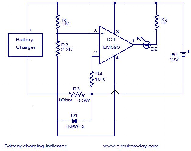
This simple circuit can be used to monitor whether a battery is charging. The voltage comparator IC LM393 is the core component of this circuit. The LED D1 will remain ON whenever there is at least 25 milliampere current...
The objective is to enhance information transmission by utilizing articles. Please contact us via email at [email protected] within 15 days if there are issues related to article content, copyright, or other concerns. Prompt action will be taken to resolve...

The design of solar panel systems with a lead-acid buffer battery is typically configured to ensure that the battery remains charged even during periods of limited sunlight. Solar panel systems integrated with lead-acid buffer batteries are designed to optimize energy...
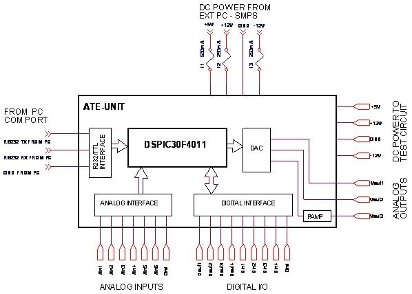
A $35 teaching aid for basic electronics, and an invaluable experimental setup for the electronics hobbyist. It teaches basic analog and digital electronics. The teaching aid is designed to facilitate the understanding of fundamental concepts in both analog and digital...
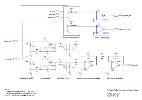
An audio compressor is designed to reduce the dynamic range of audio signals. The circuit diagram below illustrates a dynamic microphone compressor circuit that is straightforward yet delivers satisfactory results. The audio output is exceptional. This dynamic audio compressor...
This is a dry cell battery charger circuit designed to charge batteries over a period of approximately 12 hours. When powered by a 9-volt supply, the circuit is configured to accommodate AA-sized batteries. If C or D-sized batteries are...