
Low Voltage Step-Down Converter
The TPS62000 voltage regulator is designed to efficiently convert a higher input voltage to a lower output voltage, making it ideal for battery-powered devices and other applications where power efficiency is critical. This device operates using a synchronous buck converter topology, which allows for high efficiency and low output ripple. The internal reference voltage of 0.45 V is essential for setting the desired output voltage through external resistors. By adjusting the resistor values R2 and R3 according to the formula provided, the output voltage can be finely tuned to meet specific requirements.
When selecting the inductor L1, it is crucial to consider the output voltage and current requirements. A 10 μH inductor is suitable for lower output voltages, while a 22 μH inductor is recommended for outputs of 3.3 V and above to ensure stable operation and minimize output voltage ripple. The input voltage range of 2 V to 5.5 V provides flexibility for various applications, but it is important to ensure that the input voltage remains above the desired output voltage to maintain proper regulation.
The option to use fixed-output variants of the TPS62000 series simplifies the design process by eliminating the need for external resistors and capacitors, thereby reducing the overall component count and PCB space. This is particularly beneficial in compact designs where space is at a premium. The available fixed output voltages cover a range that accommodates many common digital circuits, enhancing the versatility of the TPS62000 series in powering various electronic devices. Overall, the TPS62000 voltage regulator family offers a reliable and efficient solution for applications requiring a step-down voltage conversion.Sometimes you have a situation where you have a 5-V supply voltage but part of the circuit needs a lower supply voltage. A voltage regulator from the Texas Instruments TPS62000 family [1] is a good choice for this if the current consumption is less than 600 mA.
You can thus use this device to build a very compact, highly efficient voltage converte r. A sample layout generated by the author is available as a file on the Elektor website. The TSOP62000 provides an internal reference potential of 0. 45 V, which can be used to set the output voltage in the range of 0. 5 V to 5 V by means of resistors R2 and R3. The formula for this is: Vout = 0. 45 V (0. 45 V) G— (R2 / R3) For relatively low voltages, the value of inductor L1 should be 10 H, but a value of 22 H is better if the output voltage is 3. 3 V or more. The input voltage can be anywhere in the range of 2 V to 5. 5 V, and of course it has to be higher than the desired output voltage. The output voltage is 3. 3 V with the indicated component values and an input voltage of 5 V. If you want to reduce the component count even further, you can use a member of the family with a fixed output voltage.
The available voltages are 0. 9, 1. 0, 1. 2, 1. 5, 1. 8, 1. 9, 2. 5, and 3. 3 V. With this approach you can omit R2, R3 and C3, so the output can be connected directly to pin 5. 🔗 External reference
Related Circuits
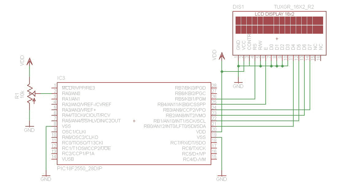
The analog to digital converter (ADC) is commonly required in most of the projects. Analog voltage measurement can be done using the ADC hardware built in together in a PIC. The picture below shows a simple setup for measuring...
This page provides basic information about voltage comparator integrated circuits and is to act as reference material for other circuits. The circuits shown are based on the LM339 Quad Voltage Comparator chip or the LM393 Dual Voltage Comparator chip....
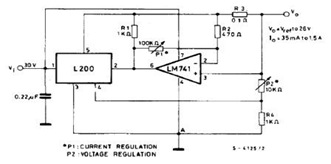
The datasheet contains application circuit diagrams for the L200, including a Programmable Voltage Regulator, a High Current Voltage Regulator with Short Circuit Protection, a Digitally Selected Regulator with Inhibit, a Programmable Voltage and Current Regulator, a High Current Regulator...
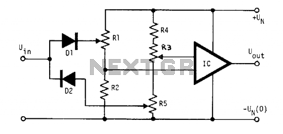
The voltage to be compared is fed through diodes D1 and D2 to the voltage dividers R1 and R5, where the low and high limits are established. When the input signal voltage exceeds the high threshold limit set with...
If you want to try a higher voltage with your pedals, try this simple and easy voltage doubler circuit which uses an ICL7660 CMOS Voltage Converter Chip. I have found that JFETs such as the J201 sound much better...
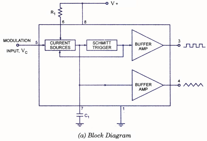
A voltage-controlled oscillator (VCO) is a type of oscillator in which the frequency of output oscillations can be adjusted by varying the amplitude of an input voltage signal. VCOs are commonly utilized in frequency modulation (FM), pulse modulation (PM),...