
A/D converter 16Bit with LCD and PIC18F2550
The analog-to-digital converter (ADC) integrated into microcontrollers, such as the PIC series, serves a crucial role in interfacing analog signals with digital systems. In applications requiring voltage measurement, the ADC converts continuous analog voltages into discrete digital values, facilitating further processing and analysis.
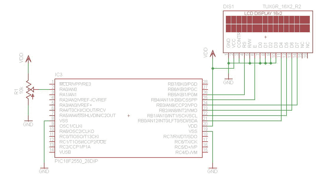
In the described setup, a 10-bit ADC is utilized, which allows for 1024 discrete values (from 0 to 1023) corresponding to the input voltage range. The configuration of the ADC begins with setting up control registers, specifically ADCON0, ADCON1, and ADCON2. ADCON0 is responsible for selecting the analog input channel (AN0 in this case) and defining the reference voltage levels (Vdd and Vss). ADCON1 configures the selected pin as an analog input, ensuring that the microcontroller interprets the voltage from the potentiometer correctly. Meanwhile, ADCON2 sets the acquisition time, which is critical for accurate readings; this value is derived from the specific microcontroller's datasheet.
Once the ADC is configured, the module must be enabled to begin operation. The conversion process is initiated by setting the GO bit in ADCON0. The conversion is complete when the ADC indicates that the process is finished, typically monitored through a status bit. The resulting digital value, which is a combination of high and low bytes, is then processed to calculate the corresponding voltage.
To convert the digital value back to a voltage, a straightforward formula is employed: the ADC result is multiplied by the reference voltage and divided by the maximum ADC value (1024). This calculation yields the voltage present at the input pin AN0. For display purposes, particularly on an LCD, the floating-point voltage value must be formatted correctly. This is achieved using the sprintf function, which formats the number into a string for presentation. Given the limitations of the C18 compiler regarding direct floating-point handling, the number is separated into its integer and fractional components before being recombined for display.
Overall, the integration of an ADC in PIC microcontroller applications provides a versatile means to measure and interpret analog signals, enabling a wide range of electronic projects and systems.The analog to digital converter (ADC) is a commonly required in most of the projects. Analog voltage measurement can be done using the ADC hardware built in together in a PIC. The picture below show a simple setup for measuring the voltage through the adjustment of the potentiometer. PIC used in this example come with a 10 bit ADC. In the picture the hex value shown is the ADC value acquired from the hardware. After a simple conversion the voltage can be obtain from this value. The next step would be to configure the register on the PIC for the ADC to operate. ADCON0 sets the refrence voltage to Vdd and Vss and select AN0 as the input for the ADC. ADCON1 configure the PIN as analog input. Only PIN AN0 is selected as analog input in this example. ADCON2 sets the required time for acquisition. The value for TAD is choose based on the calculation in the datasheet (pic18f2455, page 298-299). ADC module is turn on for it to function. To display the floating point number conversion to string must be done. The function sprintf is use to format the output so that it can be showed on the LCD. The sprintf function provided by C18 can't be used directly on a floating point number, so the number must 1st be breakup in to the digits left and right of the decimal point. The sprintf is used to join up the 2 parts and the floating point number is display out on the 2x16 lcd.
A routine for reading of ADC value is created. The acquisition is started by setting the GO bit in ADCON0. Conversion is done when the done bits turn 0. The high and low byte of the ADC results are joined in to a 16 bit data and pass back from the function. A simple formula can be use to calculate the voltage from the ADC result. The result is multiply by the max value of reference voltage and divided by 1024. Doing this will obtain the voltage on the pin AN0. 🔗 External reference
Related Circuits
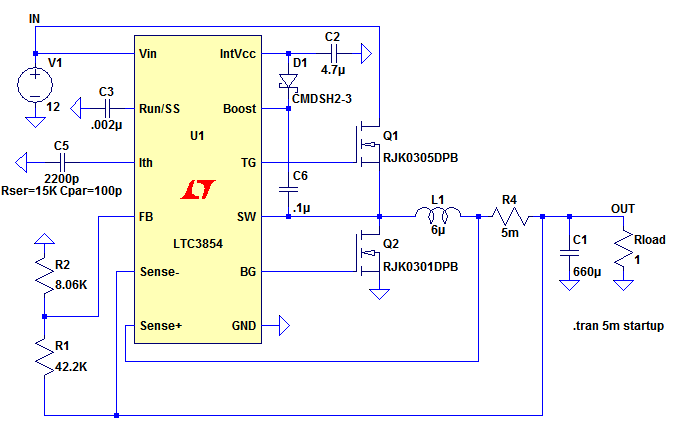
The top MOSFET activates, creating a short circuit between the input voltage (IN) and the left side of the inductor, L1. The inductor current increases according to the equation where V is the voltage across the inductor, L is...
Voltage to frequency conversion is highly beneficial in various applications, such as transmitting temperature measurements using standard voice radio transceivers. This circuit utilizes two CA3130 operational amplifiers, demonstrating satisfactory performance. The linearity of the voltage-frequency transfer is better than...
Finally I was able to control an LCD Hitachi display and a 12-key matrix keypad with only one 16F84 or 16F628. In a near future, I will be able to control a full QUERTY-type keyboard and a LCD display....

A project is underway that necessitates the conversion of a 0-10V DC supply into a linear frequency range in the form of a square wave. The project involves designing a circuit that takes a direct current (DC) voltage input ranging...
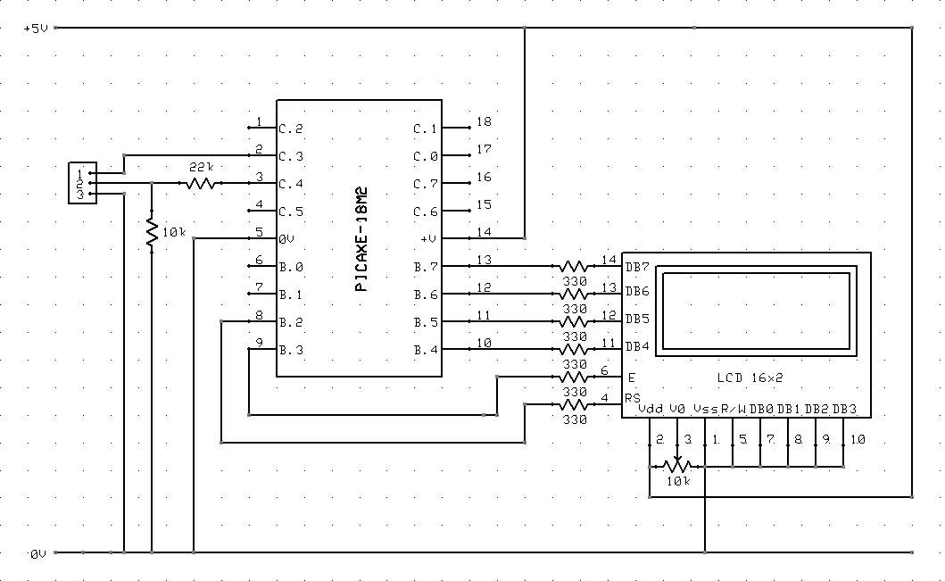
The circuit diagram and code on how to connect a 16x2 LCD to a PICAXE-18M2 microcontroller. The circuit involves interfacing a 16x2 Liquid Crystal Display (LCD) with a PICAXE-18M2 microcontroller. The 16x2 LCD is a popular display module that can...
A frequency meter can be utilized in speed sensors, tachometers, or any application that requires the measurement of repetitive signals. This frequency-to-voltage converter (FVC) is designed to facilitate the conversion process. The frequency meter is an essential instrument in various...
Warning: include(partials/cookie-banner.php): Failed to open stream: Permission denied in /var/www/html/nextgr/view-circuit.php on line 713
Warning: include(): Failed opening 'partials/cookie-banner.php' for inclusion (include_path='.:/usr/share/php') in /var/www/html/nextgr/view-circuit.php on line 713