
Luxury Car Interior Light Dimmer
The circuit for the interior light delay is designed to control the duration for which the interior lights remain illuminated after a door is closed or the ignition is turned off. It typically utilizes a combination of resistors, capacitors, and a transistor or relay to achieve the desired delay effect.
The core of the circuit involves a timing element, which can be implemented using an RC (resistor-capacitor) network. When the triggering event occurs—such as the closing of a door—the capacitor begins to charge through the resistor. The time it takes for the capacitor to reach a certain voltage level determines how long the lights will stay on. Once the threshold voltage is reached, the transistor or relay is activated, turning off the lights.
In more advanced designs, an integrated circuit (IC) may be employed to provide more precise timing control and additional features, such as adjustable delay settings or the ability to control multiple light sources. The circuit can be powered by the vehicle's battery, and it is essential to include protection components, such as diodes, to prevent back EMF from damaging the circuit when using inductive loads like relays.
Overall, this interior light delay circuit enhances the convenience and functionality of a vehicle's lighting system, ensuring that lights remain on for an appropriate period after the user has exited the vehicle.This circuit is much more modest, but certainly still worth the effort. It provides a high quality interior light delay. This is a feature that is include.. 🔗 External reference
Related Circuits
This circuit was originally available as a kit from a surplus supplier, but it is likely no longer obtainable. It incorporates several innovative concepts, such as utilizing a 555 timer as a pulse width modulator (PWM) and employing series/parallel...
This article is relevant only to readers whose bicycle lights are powered by a dynamo. The regulations regarding bicycle lights in the United Kingdom are stricter than in other countries, making the use of a dynamo uncommon in this...
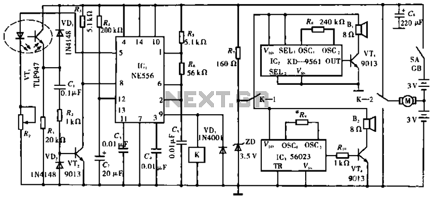
The circuit operates with VT1, which is an integrated infrared receiver, utilizing a red-emitting diode for perimeter triode reception. IC1 (NE556) functions as a dual timer, with R5, R6, and C5 forming an oscillation circuit that generates a frequency...

Bipolar +/- 15V and 5V from car battery supply power supply. Refer to the specified page for an explanation of the related circuit diagram. The described power supply circuit is designed to provide bipolar voltage outputs of +/- 15V and...

This design utilizes standard metal gate CMOS logic rather than the typical PIC or custom chip. A 22µF capacitor charges during one half of the AC cycle and provides trigger current to the triac during both halves. The circuit employs...
A 567 IC tone decoder/detector can be utilized to construct a remote control or intercom system. This circuit is capable of controlling a relay or transmitting an audio signal. The 567 IC is a versatile integrated circuit designed for tone...