
Delayed Off Light Switch

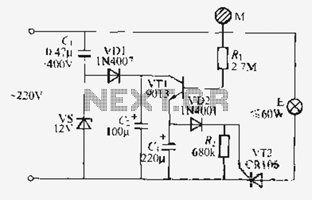
The circuit employs a straightforward yet effective approach by integrating metal gate CMOS technology, which is known for its low power consumption and high noise immunity. The use of a 22µF capacitor is critical in this design, as it acts as an energy storage element. During the positive half-cycle of the AC input, the capacitor charges up, reaching a voltage level sufficient to trigger the gate of the triac.
The triac serves as a bidirectional switch, allowing current to flow in both directions once it is triggered. This characteristic is essential for AC applications, where current alternates direction. The design ensures that the triac receives a triggering pulse during both the positive and negative half-cycles of the AC waveform. This is accomplished by utilizing the charged capacitor to deliver the necessary current to the triac gate each half-cycle.
In summary, this circuit exemplifies a unique integration of metal gate CMOS logic and passive components, providing a reliable method for controlling AC loads through a triac. The simplicity of the design, combined with the effective use of a capacitor for energy storage, offers a robust solution for applications requiring AC switching without the complexity of microcontroller-based designs.This is an unusual design in that it uses plain metal gate CMOS logic instead of the usual PIC or a custom chip. The 22uF capacitor charges up during one half of the ac cycle, and supplies trigger current to the triac on both halves.
🔗 External reference
Related Circuits

This transmitter utilizes a 741 operational amplifier as a high-gain audio amplifier, which is activated by a microphone. The output of the 741 is connected to Q1, functioning as the driver for an LED. Potentiometer R1 serves as the...
Configured with capacitive coupling by inserting a small capacitor between the phototransistor and the bipolar transistor, this relay circuit will respond only to rapid changes. This relay circuit utilizes capacitive coupling to enhance its responsiveness to fast signal changes. The...
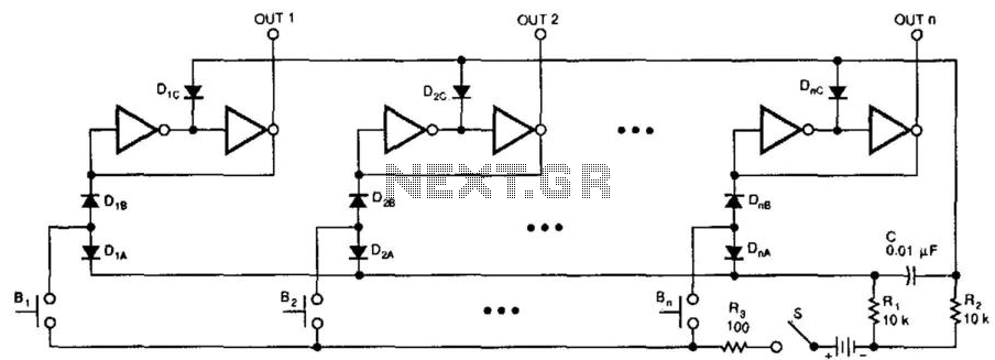
This switching circuit functions as a bank of interlocked mechanical switches. Activating one of the buttons latches its corresponding output while unlatching a previously selected output. A pair of inverters creates a latch for each output. For instance, pressing...
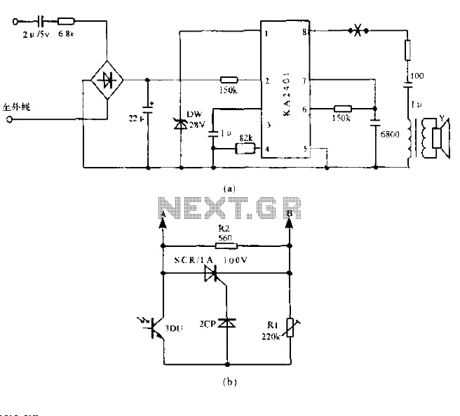
The circuit utilizes a standard telephone ringing circuit, KA2401, along with additional components to control lighting in response to a ringing signal. The light control circuit can be activated externally by AC when the ringing signal is received. The...
Utilize the call sheet to touch the electrical threshold M, which causes the E lamp to light up. When the same interval subparagraph is triggered, the lights will automatically turn off. A voltage regulator rectifier circuit is formed using...
The optically-controlled circuit plays a crucial role in urban street lighting and corridor illumination. By utilizing this circuit, lighting lamps can be automatically turned on and off based on ambient light levels, thereby reducing the need for manual control,...