
magnetic stripe reader circuit

In a magnetic stripe reader circuit, the proper configuration of components is critical for accurate operation. The circuit typically includes a magnetic sensor, a signal processing unit, and an output interface. The transistor plays a vital role in amplifying the signal received from the magnetic stripe reader.
In this particular wiring diagram, the transistor's collector is connected to the tip pin of the jack, which serves as the output connection to the next stage of the circuit or to an external device. This connection is essential for transferring the amplified signal generated by the transistor.
The base pin of the transistor is connected to the junction of a 120,000-ohm resistor and a 470-nanofarad capacitor. This configuration forms a biasing network that controls the transistor's operation. The resistor limits the current flowing into the base, while the capacitor couples the AC signal from the magnetic stripe reader to the base of the transistor. This allows the transistor to switch on and off in response to the magnetic stripe's information, effectively converting the analog signal into a digital format that can be processed further.
It is crucial to ensure that the transistor is correctly wired in the circuit to avoid malfunction. The absence of a connection to the transistor may lead to a failure in signal amplification, rendering the magnetic stripe reader ineffective. Proper attention to the component values and connections will facilitate a reliable and efficient operation of the magnetic stripe reader circuit.magnetic stripe reader, electric circuit theory, logic operation: Your wiring diagram does not connect the transistor in the circuit. The collector pin of the transistor connects to the tip pin of the Jack. The base pin of the transistor connect to the junction of the 120,000 ohm resistor and the 470 nanofarad capacitor..
🔗 External reference
Related Circuits

This power supply employs two VN400A 400-Volt MOSFETs arranged in a half-bridge configuration. The outputs provide +5V at 20A and +15V at 1A. Low-current outputs utilize three-terminal regulators, allowing for either 12 Volts or 15 Volts to be achieved...
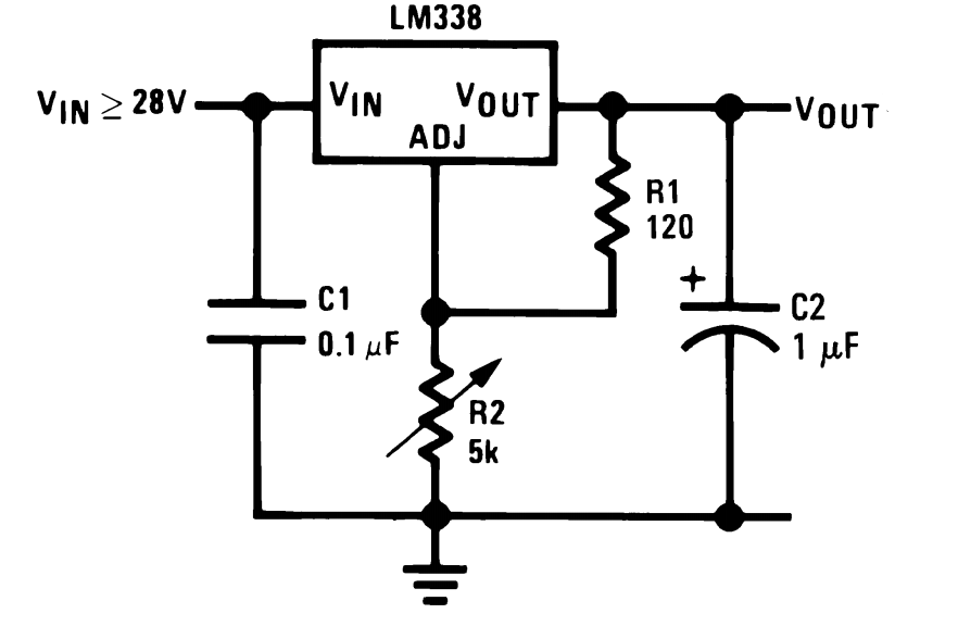
The LM338 integrated circuit (IC) from Texas Instruments is a versatile component that can be configured in various ways to create high-quality power supply circuits. The first circuit demonstrates the typical wiring format around the IC, providing an adjustable...

This project involves a compact, portable DJ mixer that can be powered by a 9V DC external supply adapter or a 9V PP3 battery. The mixer includes two stereo phono inputs, two stereo line-level inputs, and a single stereo...

This is a small circuit designed as an insect repellent, targeting mosquitoes and birds by producing high-frequency audio signals. These signals interfere with the hearing of insects, making it unbearable for them, causing them to flee. The operation of...
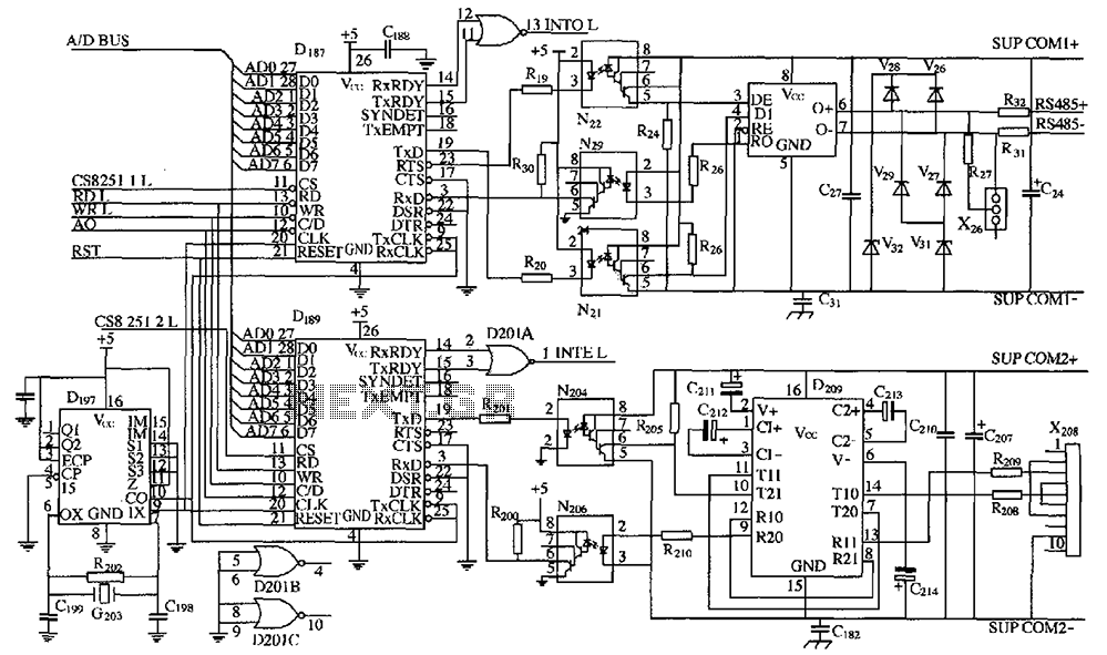
As shown in the figure, D187 is a universal asynchronous receiver-transmitter (UART). Its RX/TX signals are received through optocouplers N21, N22, and N29, facilitating RS-485 communication. The interface receiver/transmitter D28 and microprocessor D211 are completely optically isolated. D197 serves...
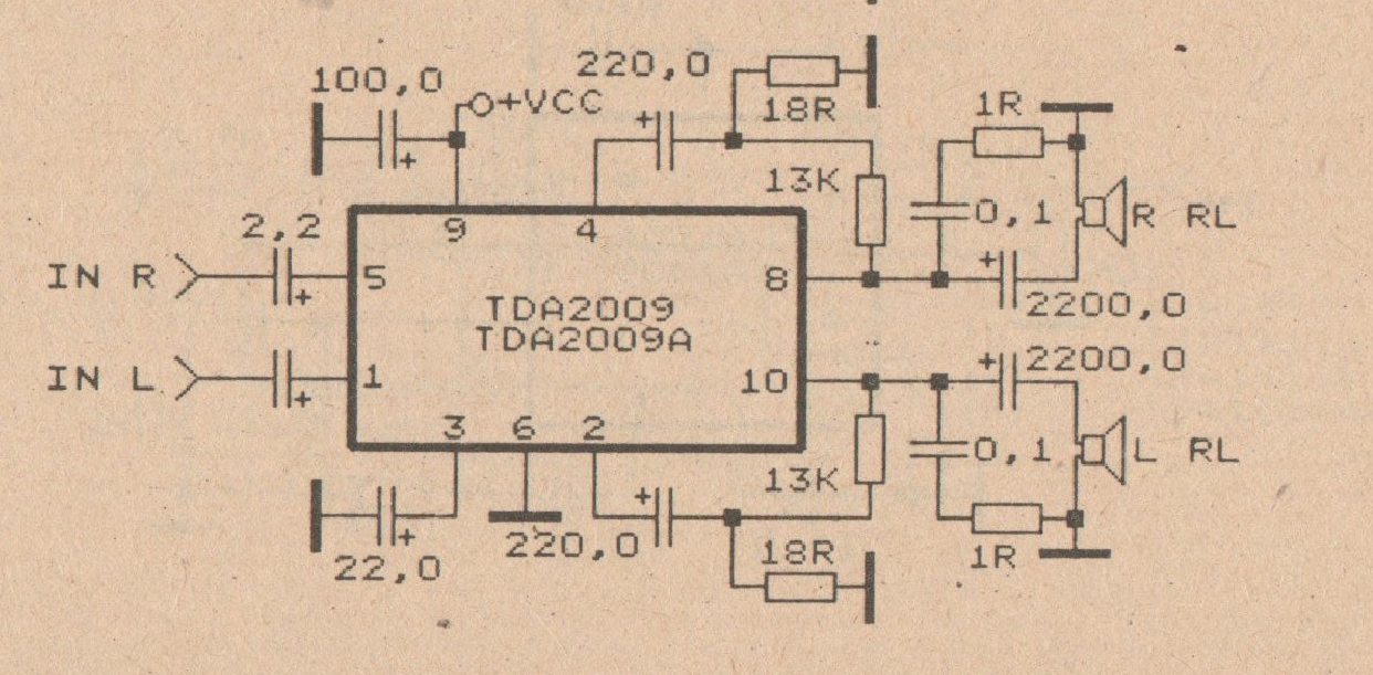
The minimum voltage required for this circuit is 8 volts, while the maximum voltage is 28 volts. It can be used to amplify audio signals in electronic devices such as radios, DVDs, MP4 players, and MP5 players. The circuit...
Warning: include(partials/cookie-banner.php): Failed to open stream: Permission denied in /var/www/html/nextgr/view-circuit.php on line 713
Warning: include(): Failed opening 'partials/cookie-banner.php' for inclusion (include_path='.:/usr/share/php') in /var/www/html/nextgr/view-circuit.php on line 713