
Circuit Compact DJ Station

The circuit design of the portable DJ mixer is structured to facilitate ease of use and flexibility in audio mixing. The two stereo phono inputs are intended for connecting turntables, while the stereo line-level inputs accommodate various audio sources, ensuring versatility in input options. The mixer’s architecture allows for seamless transitions between audio sources, making it ideal for live performances or studio settings.
The phono amplifier module plays a crucial role in ensuring high fidelity when using vinyl records, adhering to the RIAA equalization curve to provide accurate sound reproduction. The LS4558 dual IC is chosen for its low noise and distortion characteristics, making it suitable for high-quality audio applications.
The headphone amplifier module is designed to provide clear monitoring capabilities without significant power draw, allowing for extended use without rapid battery depletion. The 5532 dual IC is utilized for its ability to deliver substantial power while maintaining low distortion levels, critical for accurate monitoring during live mixing.
The mixing functionality, facilitated by the crossfader and independent level controls, allows the DJ to creatively blend audio signals. The design ensures that the audio signals can be manipulated intuitively, providing a dynamic mixing experience. The inclusion of a microphone input further enhances the mixer's capabilities, allowing for live vocal performances or announcements.
Overall, the portable DJ mixer is engineered for reliability and performance, with thoughtful consideration given to component selection and circuit design to meet the demands of both amateur and professional audio mixing applications.This project consists of a small, portable DJ mixer powered by a 9V dc external supply adaptor or from a 9V PP3 battery. The mixer features two stereo phono inputs and two stereo line-level inputs and has one stereo mixing channel.
A microphone input and a stereo main output with adjustable gain are also provided. Headphone monitoring includes a c ue switch for selecting Channel 1, Channel 2 or Master Channel. For easy understanding, the circuit is divided into five blocks, as follows: General Circuit diagram:all passive circuitry (controls, faders, switches, input and output connectors) is shown in full, whereas active amplification modules are represented by suitably labeled triangle symbols. Phono Amplifier Module: a high gain stereo amplifier suitable for moving magnet pick-up cartridges, having a frequency response according to RIAA equalization curve and based on the low noise, low distortion LS4558 dual IC.
Two identical stereo modules of this type are required. Headphone Amplifier Module: this circuit was already present on this website under Portable 9V Headphone Amplifier. It features a low current drain stereo amplifier based on the low distortion, low noise 5532 dual IC, capable of delivering 3.
6V peak-to-peak into 32 Ohm load at 9V supply (corresponding to 50mW RMS) with less than 0. 025% total harmonic distortion (1kHz & 10kHz). The input source can be selected by means of SW1 for Channel 1 and SW2 for Channel 2. Moving magnet pick-ups must be connected to Phono 1 and 2 inputs, whereas CD players, iPods, Tape recorders, PC Audio outputs and the like can be connected to Line 1 and 2 inputs. After a separate Level control for each channel (P1 and P2), the two incoming audio signals are mixed and cross-faded by means of P3 and associated resistors network.
The Crossfader control mixes both Channels at the same intensity when set in the middle position. When the cursor of P3 is fully rotated towards R3-R4, only Channel 1 signal is present at the Main output, whereas Channel 2 is muted. Conversely, Channel 2 signal is present at the Main output and Channel 1 is muted when the cursor of P3 is fully rotated towards R1-R2.
This network is followed by the Mixer Amplifier, the Master Level P4 and the Main output sockets. A low impedance microphone can be connected to the Mic input. P6 controls the signal level after amplification by the Microphone Amplifier module and feeds the Left and Right Mixer Amplifiers through R9-R10. In this way, the speakers voice will be reproduced at the center of the soundstage. A stereo Headphone Amplifier with cue gain control is provided for monitoring purposes. The Cue Select switch SW3 will allow Headphone reproduction of Channel 1, Channel 2 or Master Channel, independently of the signal present at the Main Output.
J13 is a Mini DC Power Socket into which the suitable plug of a 9V dc external supply adaptor should be inserted. In any case, due to the low total current drain (about 13mA average), a 9V battery can be used satisfactorily to power the entire Station.
A more strict RIAA equalization curve will be obtained if low tolerance components are used for R5, R6, R7, R14, R15, R16 (1% - 2%) and C3, C4, C8, C9 (2% - 5%). 🔗 External reference
Related Circuits
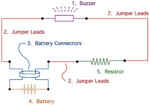
The drive circuit is a basic drive recently designed to accommodate a 27mm passive piezoelectric buzzer, aiming for a sound output exceeding 100dB while minimizing power consumption. Due to constraints related to product cost and structural size, the circuit...
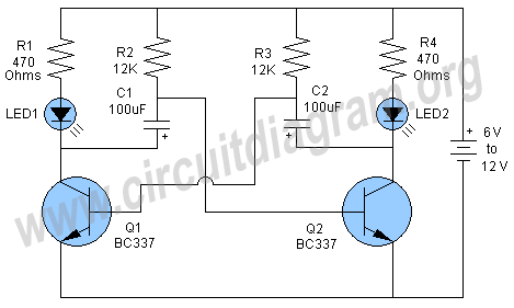
A schematic of a flip-flop LED flashing circuit is presented. This circuit functions as an astable multivibrator that activates LEDs sequentially upon power application. It is compatible with voltage inputs ranging from 6 to 12 volts, and can also...
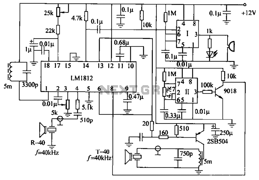
The ultrasonic anti-collision circuit is designed using the LM1812 integrated circuit, which controls both the transmission and reception functions. A distance control potentiometer allows for adjustments within a range of 2 to 3 meters. The timebase circuit is constructed...
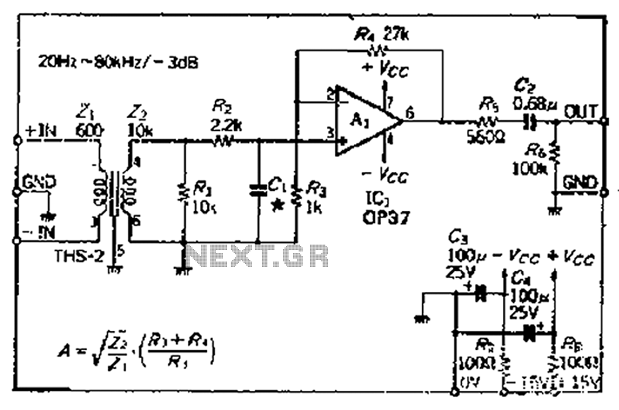
The common mode signal rejection ratio is influenced by the input transformer, which should either be a commercially available or a well-balanced homemade transformer. It is important to note that as frequency increases, the balance may decrease. The transmission...
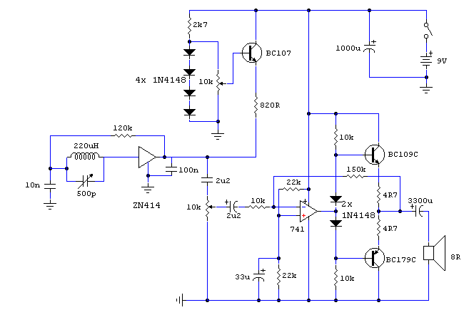
This receiver is designed around the widely used ZN414 integrated circuit (IC) and operates within the AM band, covering frequencies from 550 to 1600 KHz. To utilize the receiver for Longwave frequencies, it is necessary to replace the coil...

The preamplifier circuit is designed to offer appropriate loading for phono cartridges with reluctance. It achieves a gain of approximately 25 dB at 1 kHz (converting an input of 2.2 mV to an output of 100 mV). The circuit...