
mains pulse circuit

This circuit functions effectively as a programmable timer switch for mains-operated devices. The design incorporates a transformer (Tr1) that steps down the mains voltage to a lower level suitable for rectification. The bridge rectifier converts the alternating current (AC) from the transformer into direct current (DC), which is then regulated to a stable 12V by regulator IC1, ensuring that the timer circuit operates reliably.
The timer circuit utilizes a timer IC (IC2), typically a 555 timer or similar, configured in astable or monostable mode, depending on the desired application. The independent charging and discharging of the timing capacitor allows for flexibility in timing intervals. The use of jumpers to select different capacitors enables quick adjustments to the timing range, accommodating various operational requirements.
The two preset potentiometers provide user-friendly control over the on and off durations, allowing for precise adjustments based on the specific needs of the application. The inclusion of a 1k resistor in series with one of the potentiometers ensures that the discharge time remains within safe limits, preventing potential damage to the components.
The relay controlled by the timer IC features double-pole contacts, allowing for the switching of the mains voltage supply to the connected equipment. The LED indicators serve as a visual cue for the operational status of the circuit, enhancing user interaction and safety.
Protection measures are also integrated into the design. A 100mA slow fuse is employed to safeguard the mains transformer and low-voltage components from overcurrent conditions, while a 4 A medium slow fuse protects the relay from potential overload situations, ensuring the overall reliability and longevity of the circuit. This circuit is ideal for applications needing automated control of mains-powered devices, providing both functionality and safety in its operation.This is a circuit that used to main pulse. The pulser is intended to switch the mains voltage on and off at intervals between just under a second and up to 10 minutes. This is useful, for instance, when a mains-operated equipment is to be tested for long periods, or for periodic switching of machinery.
Transformer Tr1, the bridge rectifier, and r egulator IC1 provide a stable 12V supply rail for IC2 and the relay. The timer is arranged so that the period-determining capacitor can be charged and discharged independently. Four time ranges can be selected by selecting capacitors with the aid of jumpers. Short-circuiting positions 1 and 2 gives the longest time, and short-circuiting none the shortest. Here`s the figure of the schematic circuit diagram; In the latter case, the 10 µF capacitor at pins 2 and 6 of the timer IC determines the time with the relevant resistors.
The value of this capacitor may be chosen slightly lower. The two preset potentiometers enable the on and off periods to be set. The 1k resistor in series with one of the presets determines the minimum discharge time. The timer IC switches a relay whose double-pole contacts switch the mains voltage. The LEDs indicate whether the mains voltage is switched through (red) or not (green). The 100mA slow fuse protects the mains transformer and low-voltage circuit. The 4 A medium slow fuse protects the relay against overload. 🔗 External reference
Related Circuits
A 2002 Blazer was diagnosed with error codes P0155 and P0756, indicating a malfunction in the O2 sensor heater circuit and a performance issue with the shift solenoid B circuit. The vehicle initially has power, but it loses power...

Remote Control Mains Switch The remote control mains switch is a device designed to control the power supply to electrical appliances from a distance, typically utilizing a wireless remote control. This switch can be integrated into various applications where remote...
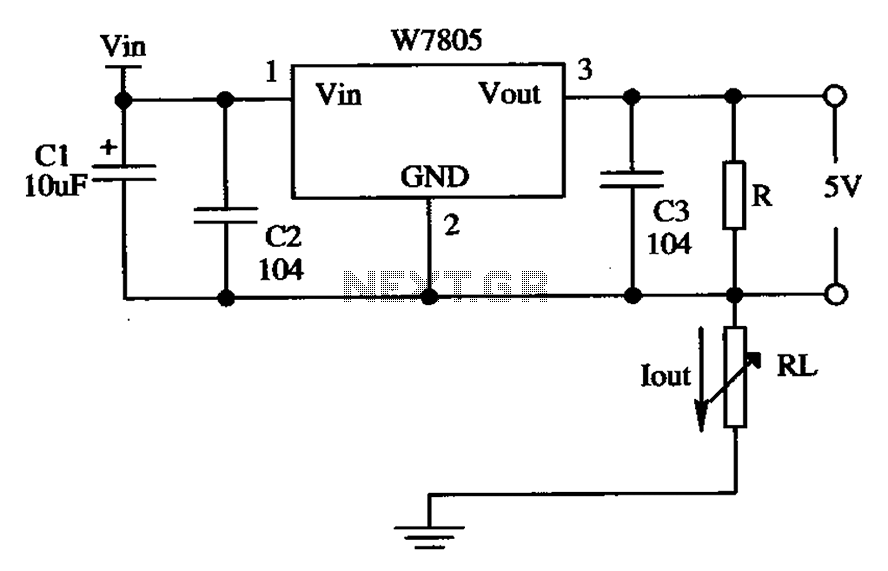
The circuit is composed of a W7805 positive current source application integration circuit that includes a voltage regulator. The W7805 regulator operates in suspension. A resistor is placed between its output terminal and the common terminal, forming a constant...
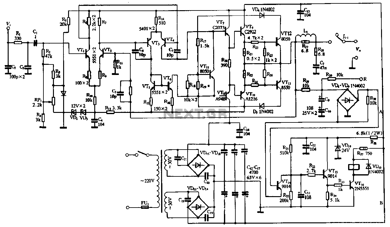
The performance of the amplifiers 2SC2922 and 2SA1216 (or 2SC3264 and 2SA1295) is excellent, featuring good linearity and strong overload capabilities. These devices are utilized as high-fidelity power amplifier stages, demonstrating outstanding performance. The circuit, as illustrated in Figure...
Electrical signals travel along the neurons in the brain and body, continuously transmitting information throughout the complex system. Without these signals, the body would function like a plant, with different parts unaware of each other's conditions, making animal life...

The AC power supply voltage is normal, and a relay is connected to the load (Rfz) circuit. In the event of a load short-circuit failure, the voltage across relay KA drops rapidly, causing KA to release and disconnect the...