
Simple AC short circuit protection

The described circuit serves as a protective mechanism for electrical systems, specifically designed to monitor the load connected to an AC power supply. The relay (KA) acts as a switch that controls the connection between the power supply and the load (Rfz). Under normal operating conditions, the relay remains energized, allowing current to flow to the load.
In the event of a short circuit, which is characterized by a sudden drop in resistance, the voltage across the relay coil (KA) decreases sharply. This voltage drop triggers the relay to de-energize, effectively opening the circuit and disconnecting the load from the power supply. This rapid response is crucial for preventing damage to the load and reducing the risk of fire or other hazards associated with electrical faults.
The LED tube (VL) serves as a visual indicator of the short-circuit condition. When the relay releases due to the voltage drop, the LED is powered, illuminating to alert users of the fault condition. This feature enhances the safety and reliability of the system, allowing for immediate identification of issues that require attention.
Overall, this circuit design is essential for ensuring the protection of electrical loads in AC power applications, providing both automatic disconnection in fault conditions and visual feedback for maintenance and troubleshooting purposes.AC power supply voltage is normal, relay, connected to the load (Rfz) circuit. When the load short-circuit failure, KA voltage drop across quickly, KA release, cut off the load circuit. Meanwhile, the light emitting diode tube VL lights indicating the short circuit occurs.
Related Circuits
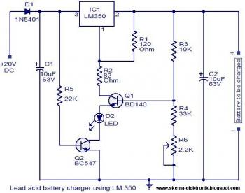
The circuit is designed as a constant voltage source with a negative temperature coefficient. The transistor Q1 (BD 140) serves as the temperature sensor, while transistor Q2 prevents battery discharge through resistor R1 when mains power is unavailable. The...
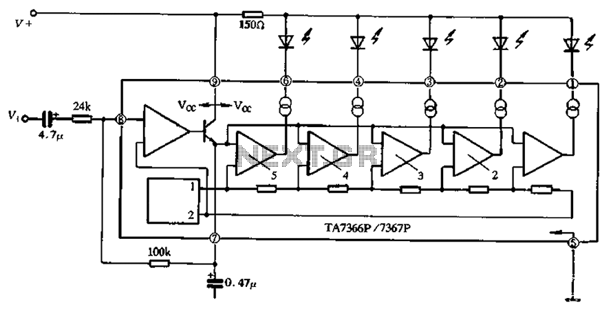
The TA 7366/7367 is a commonly used single display driver circuit manufactured by Toshiba Corporation. It features a 5 LED driver circuit and is designed in a 9-pin single in-line plastic structure. The circuit configuration includes an operational amplifier...
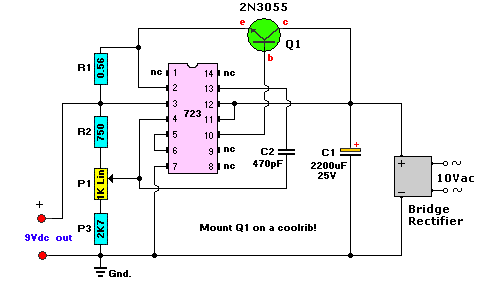
This AC to DC power supply can output 5A in continuous operation and 12A peak current. This type of DC power supply uses a PCB, allowing for two case types. The described AC to DC power supply is designed to...
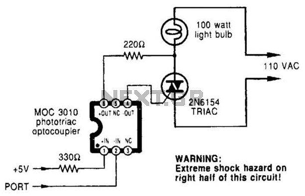
A microcomputer-to-triac interface utilizes a phototriac optoisolator to safely isolate logic signals, allowing direct control of high-power loads. This circuit can function as either an on/off switch or a proportional phase control, depending on the input waveforms and the...
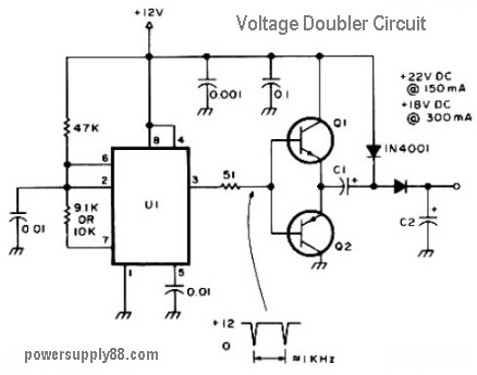
The schematic diagram originates from a 12V DC voltage doubler circuit power supply. This circuit diagram illustrates a DC voltage doubler/DC converter that transforms a 12V DC power supply into 24V DC and 18V DC outputs. It is compatible...
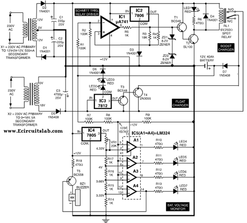
This circuit illustrates the use of the 7806 IC in an automatic battery charger circuit diagram. It is designed for a car battery with an approximate rating of 40 Ah. The automatic battery charger circuit utilizing the 7806 integrated circuit...