
Making The LCD Expansion Board for PIC18F4520

The assembly begins with soldering a 40-pin right-angled Berg housing onto the expansion board to connect it with the PIC development board. A 16-pin Berg housing is then soldered to attach the LCD module. Berg housings are available in 40-pin configurations and should be carefully cut using a small hacksaw blade or a sharp hot knife. Each pin of the LCD must be connected to the corresponding PIC I/O ports as indicated in the provided schematic. The LCD pin numbers and names are printed on the module itself. Similarly, other expansion modules can be created to connect to the PIC development board, enhancing its functionality. The expansion boards can be interchanged quickly, allowing for the transformation of projects without significant downtime. Various projects can be stored on separate expansion boards, while the CPU core unit remains consistent, eliminating the need for repeated investment in that component.
The expansion board serves as a versatile interface for integrating a 16x2 LCD module with a PIC microcontroller, facilitating the display of alphanumeric characters in various applications. The design emphasizes modularity and ease of use, allowing users to rapidly prototype and iterate on their projects. The inclusion of a variable resistor for contrast adjustment is a critical feature, ensuring optimal visibility of the displayed information under different lighting conditions. The optional series resistor for the backlight enhances usability in low-light environments, making the LCD module suitable for a wider range of applications.
The schematic should clearly illustrate the connections between the PIC microcontroller's I/O ports and the LCD module, ensuring that users can follow the layout with precision. The labeling of ports and connections on both the expansion board and the LCD module simplifies the assembly process, making it accessible even to those with limited experience in electronics. This expansion board not only supports the immediate need for an LCD display but also encourages further exploration and development of additional modules, fostering a deeper understanding of microcontroller interfacing and electronics design. The ability to interchange expansion boards without replacing the core microcontroller unit significantly reduces project turnaround time and cost, making it an invaluable tool for hobbyists and professionals alike.A very useful expansion board for our PIC development board. It will be a Do It Your self (DIY) LCD Expansion board. The expansion board can be plugged into the PIC development board to add 16x2 Alphanumeric LCD Support to it. Since LCDs are required in many projects and experiments it will be a very helpful board. I recommend you to read the LCD Interfacing Tutorial before you proceed. It will give you an Idea how LCD is connected to PIC Microcontrollers. So lets start! The board is very easy to make as the MCU core unit is already done for you. So you need to just care about the LCD part. It consists of the 16x2 LCD Module and A variable resistor (10K) only! Optionally you can add a 47ohm series resistor with the LED backlight of the LCD Module, to enable the backlight. The variable resistor is used to adjust the contrast of the module. If NO text is displayed adjust this pot. As you can see the top row in the board lists all I/O port of PIC MCU like, RB7, RA1 etc. For Example, RB7 stands for Port B 7th bit. The row also has regulated 5v supply and GND outputs. So we start by soldering a 40 PIN Right Angled Burg Housing on the Expansion Board. This will help connect it with the PIC development board. On the expansion board we solder a 16 PIN Burg Housing, this will help attach a LCD Module. Burg Housing is available in 40 PINs, you have to safely cut it using a small hacksaw blade or a sharp hot knife.
After that connect each PIN of the LCD with the PIC I/O Ports as shown in the schematic given above. The LCD PIN number and name are printed on the module it self. In the same way we created the LCD Expansion board you can create any other expansion module to hook in your PIC Development board and extend its capabilities. You can remove one expansion board and hook up another to change it to a completely new project in NO time.
You can store a number of project separate on different expansion boards. The CPU core unit is always reused so you don`t have to invest in it each time. 🔗 External reference
Related Circuits
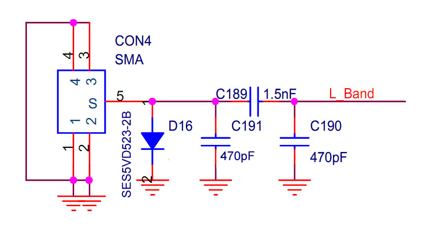
The implementation occurred in the higher frequency L-band (1452-1492 MHz), while the EU, AU, and GB operate in the VHF Band III (174-230 MHz). Unfortunately, it did not succeed for various reasons. The application works well locally, but only...
The clip sync output to TTL level appears to require additional time to accommodate extra components on the board. As a temporary solution, a ZPD4.7 (4.7 V Zener Diode) should be placed between SG and ground at the power...
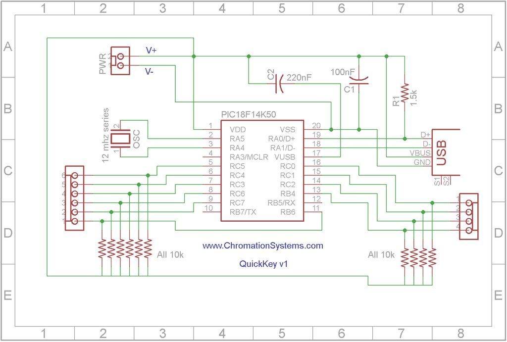
Quick Key Adapter, 10 Button HID Keyboard. This document outlines the process of creating a USB-connected Human Interface Device (HID) keyboard featuring 10 button inputs. The Quick Key Adapter is designed to facilitate user interaction through a compact keyboard interface....
Humanity has long grappled with the concept of Time, often seeking ways to interact with it meaningfully. A proposed solution is a knocking platform designed to address these fundamental needs, exemplified by the Knock Block KUI and its associated...

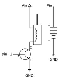
This relay driver enhances the input impedance using a standard BC547 NPN transistor (or its equivalent). It is a widely used driver capable of operating various relays, including reed relays. Transistors Q1 and Q2 function as a simple common-emitter...
The LM35 from National Semiconductor is a precision centigrade temperature sensor that provides an analog output voltage. It operates within a temperature range of -55°C to +150°C and has an accuracy of ±0.5°C. The output voltage corresponds to 10mV...