
Mazda 626 1994 Wiring Diagram

The wiring schematic for the 1994 Mazda 626 serves as an essential resource for understanding the vehicle's electrical system. The diagrams illustrate the interconnections between various components, allowing for effective troubleshooting and repair.
The 2.0L engine wiring diagram includes the layout for critical systems such as the air conditioning (A/C) circuit and heater circuit. The A/C circuit encompasses the compressor, condenser, evaporator, and associated relays and switches, providing a detailed view of the refrigerant flow and electrical control.
The heater circuit diagram outlines the connections for the heater core, blower motor, and temperature control switches, ensuring proper operation of the vehicle's heating system.
For the 2.5L engine configuration, the wiring diagram similarly details the A/C circuit, providing insight into the additional components that may be present due to the increased engine size.
The anti-lock brake system (ABS) circuit is crucial for vehicle safety, and the schematic includes the connections for the wheel speed sensors, ABS control module, and hydraulic control unit, helping to ensure the proper functioning of the braking system under various conditions.
Additionally, the anti-theft circuit is represented, detailing the components involved in securing the vehicle against unauthorized access. This includes the alarm system, immobilizer, and any related sensors.
Overall, the comprehensive wiring diagrams for the 1994 Mazda 626 facilitate a deeper understanding of the vehicle's electrical architecture, enabling technicians and DIY enthusiasts to perform maintenance and repairs with confidence.The following document is very complete car wiring of Mazda 626 year 1994. Here the diagrams which is contained in Mazda 626 car wiring diagram: 2.0L, A/C Circuit Heater Circuit 2.5L, A/C Circuit Anti-lock Brake Circuits Anti-theft Circuit.. 🔗 External reference
Related Circuits
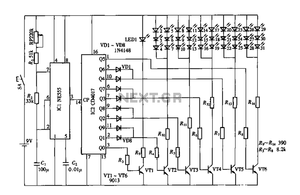
An electronic decorative peacock consists of 10 light-emitting diodes (LEDs), each of which contains multiple LEDs arranged in the tail of the peacock model. The light emission drive circuit operates the fan-shaped LEDs in a cyclic manner, emitting light...
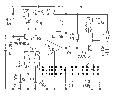
This article discusses the functionality of a super-regenerative FM receiver. The principle behind this receiver utilizes high-gain miniature integrated circuits, resulting in a simple and innovative circuit design. It achieves the performance level of standard FM receivers while addressing...
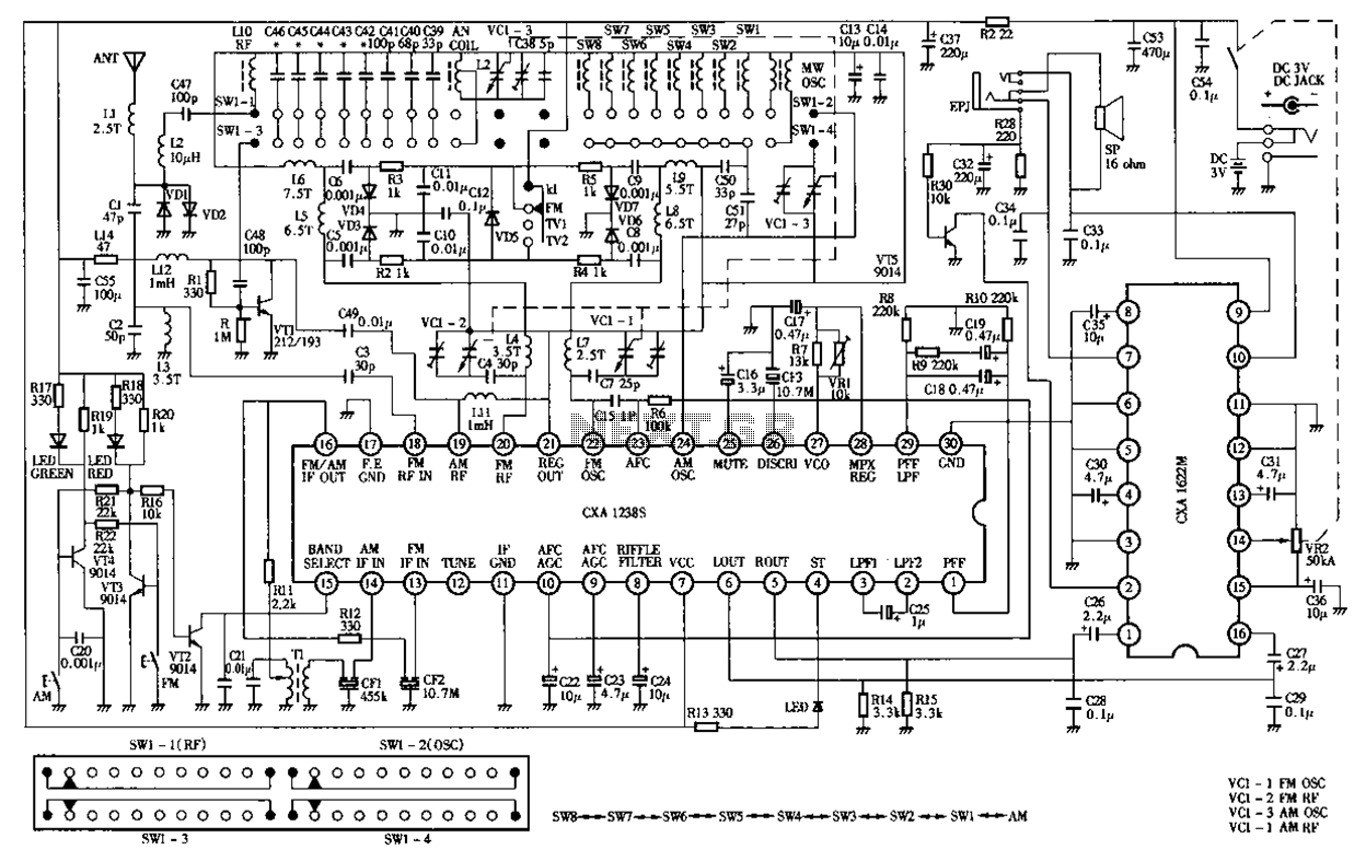
Desheng Rl212A 12-band FM, MW, SW, television sound stereo radio circuit diagram as follows: The Desheng Rl212A is a versatile radio circuit designed to operate across 12 different frequency bands, including FM (Frequency Modulation), MW (Medium Wave), and SW...
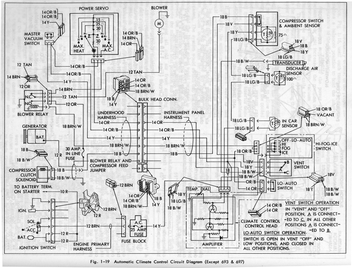
Gerald's 1958 Cadillac Eldorado Seville, 1967 Cadillac Deville, 1967 Eldorado, and 1971 Lincoln Continental Mark III - everything you always wanted to know about these cars. The 1958 Cadillac Eldorado Seville is a classic American luxury vehicle renowned for its...
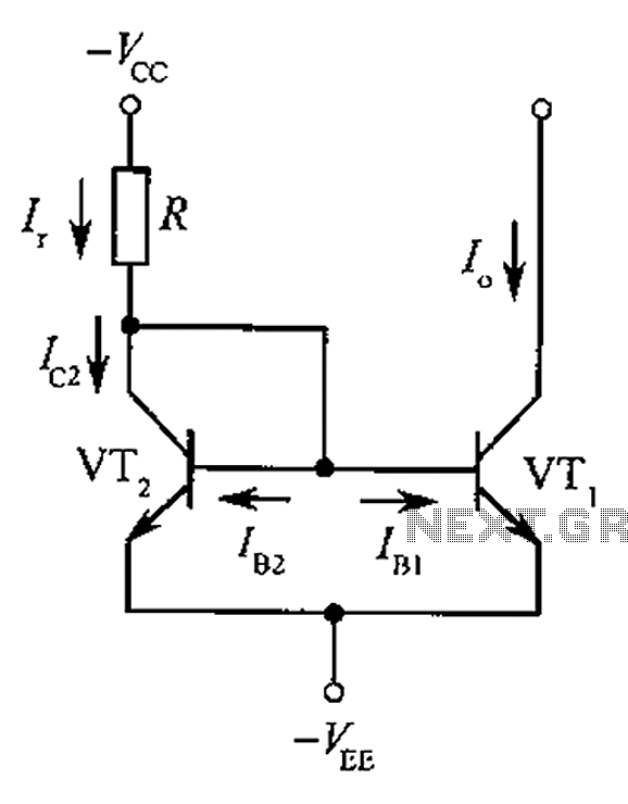
The circuit depicted is a mirror substantially constant current source circuit, in which transistors VT1 and VT2 are matched to each other. The figure illustrates that the current through Ir is equal to Ic2 plus the sum of base...
The layout design of the TIQ Flash ADC closely follows the provided circuit diagram. A row layout is implemented, with rows stacked on top of each other. Each row comprises a comparator, a gain booster, a 0-1 generator, and...