
Tachometer circuit diagram of a multiplier

The National Semiconductor LM2907 is a versatile frequency-to-voltage converter that can be effectively employed in various digital control systems. When a sine wave input is applied to the zero electromagnetic pickup, the LM2907 processes this signal to produce a corresponding output pulse. The frequency of the input signal determines the pulse width, which is directly influenced by the capacitance value of capacitor C1 in the circuit.
In practical applications, the output pulse width can be adjusted by varying the capacitance of C1, allowing for fine-tuning of the circuit's response to different input frequencies. The power supply voltage applied to the circuit is also critical, as it affects the overall performance and stability of the LM2907. A stable power supply ensures that the output pulse remains consistent, which is essential for reliable operation in digital control systems.
Furthermore, this circuit serves as a multiplier for microprocessor control systems, enabling the integration of analog signals into digital processing environments. By converting the frequency of the input sine wave into a pulse width that can be read by a microprocessor, it allows for the implementation of complex control algorithms and feedback systems. This capability is particularly useful in applications such as motor control, signal processing, and automated systems where precise timing and control are required.
Overall, the LM2907 circuit's ability to generate output pulses based on sine wave inputs makes it a valuable component for engineers designing advanced electronic control systems.After each zero electromagnetic pickup has a sine wave input, as shown in the National Semiconductor LM2907 circuit will produce an output pulse, the circuit can be used for di gital control system in. Width of each pulse is a C1 size and the power supply voltage used in the decision. Circuit is a multiplier for the microprocessor control system services.
Related Circuits
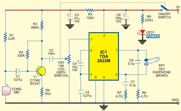
This is a cost-effective DIY option for a hearing aid. It should not be considered a replacement for a genuine hearing aid prescribed by an audiologist. Amplifying all sounds and frequencies, or using it continuously in loud environments, may...
This PC fan controller circuit is designed with discrete components to control 12V fans that consume less than 200mA. The specified component values in the circuit diagram ensure that the voltage will not drop below 7V. If the fan...
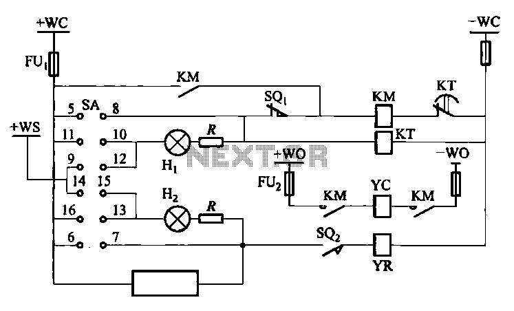
The DW10M de-excitation type switch is based on the DW10 automatic air circuit breaker, transitioning from normally open to normally closed contact. The models available include DW10M-200, DW10M-400, and DW10M-600. The control circuit for this type switch is illustrated...
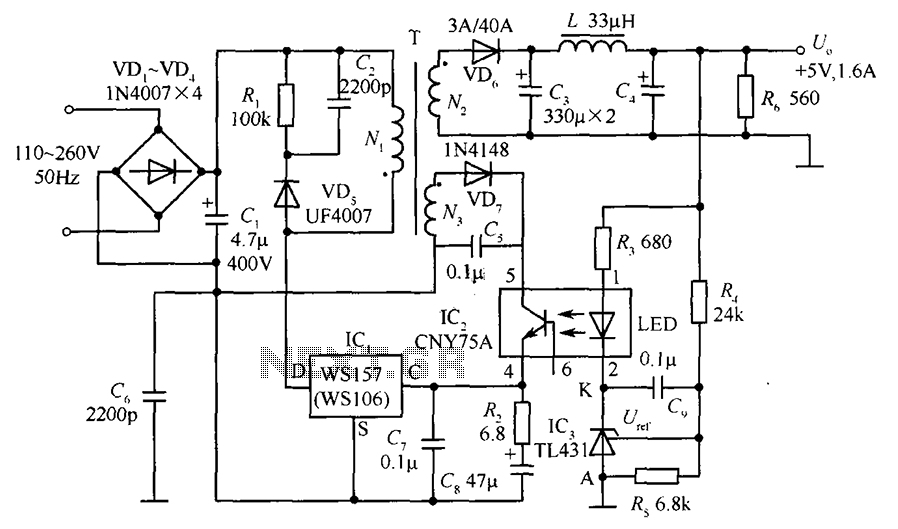
The circuit incorporates an optical coupler (CNY75A) and an adjustable precision shunt regulator (TL431). It includes current limiting resistors R3, R4, and R5 for the sampling resistor. As the output voltage (Uo) varies, the voltage across the sampling resistor...
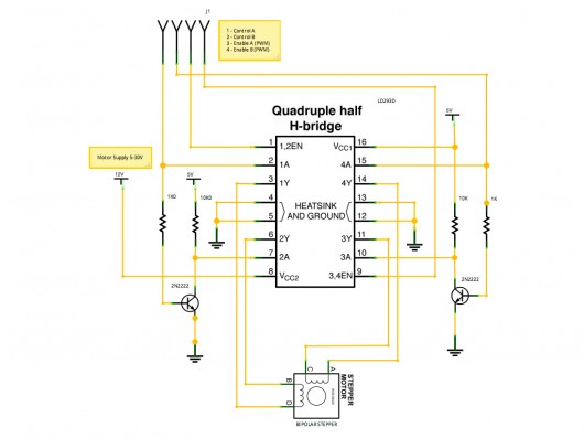
A stepper motor controller based on schematics available on the Arduino website. Initially, a two-pin configuration was attempted for a bipolar stepper motor, but it did not function as expected, especially with the library provided on the site. The...
The circuit depicted is designed to protect a system from power supplies that may exceed safe limits. An example of this is small consumer products that utilize external AC adapters, where there is a risk of accidentally connecting the...