
Circuit Detector and Disconnecting Over Voltage Schematic

This circuit serves as an essential safeguard for electronic devices, particularly those vulnerable to voltage fluctuations from external power sources. The use of the LM4041 as a voltage reference ensures precise detection of voltage levels, allowing for reliable operation under varying conditions. The careful selection of resistors R1 and R2 is crucial, as these components define the voltage threshold for system shutdown. By implementing R3, the circuit maintains stability and prevents unnecessary interruptions caused by minor voltage variations.
The inclusion of resistor R4 is a strategic design choice, providing hysteresis to the system. This feature is vital in applications where the supply voltage might fluctuate around the shutoff threshold, as it prevents rapid on-off cycling that could lead to potential damage or operational instability. The design also accommodates a wide range of supply voltages, making it versatile for various applications.
In summary, this protection circuit is an effective solution for managing power supply risks in consumer electronics and portable devices, ensuring that they operate within safe voltage limits while maintaining functionality and reliability.The circuit in this figure is protecting the circuit and the system with power supplies that may exceed safe limits. One example is small consumer products that use external ac adapters; its easy to mistakenly plug in the wrong adapter.
Another example is a portable system that uses a rechargeable battery pack. If the battery pack is absent or fai ls to open during recharging, a high-compliance charger can deliver excessive voltages to the system. The circuit works using LM4041 adjustable shunt-voltage regulator as a voltage detector. When it operates as a reference, the LM4041 develops a voltage across its positive and negative terminals.
This signal forces the voltage across R1 to equal 1. 24V. In this circuit, however, R3 prevents this servo action. With R3 in the circuit, VG is near ground when the voltage across R1 is less than 1. 24V, and VG is approximately 1V below the positive rail when the voltage across R1 is greater than 1. 24V. You can, therefore, set a threshold voltage by selecting appropriate values of R1 and R2. When the supply voltage exceeds the threshold, VG goes high, thereby turning off Q1 and removing power from the load.
Select R1 and R2 according to: It where VSHUTOFF is the supply voltage that causes shutoff. With the values shown, the circuit removes power from the load when the supply voltage reaches approximately 6V. R4 provides hysteresis to prevent chattering when the supply voltage is near the shutoff value. IC1 can accommodate shutoff voltages as high as 10V; clamping IC1s supply voltage with another inexpensive shunt reference or zener diode (across the positive and negative terminals) allows higher maximum shutoff voltages.
Maximum supply voltage with the components is approximately 50V. 🔗 External reference
Related Circuits
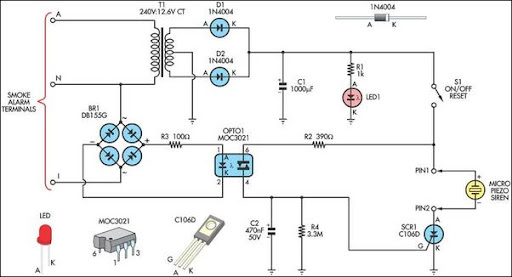
This alarm circuit was designed to monitor a mains-powered smoke detector located in a shed used for dog kennels. It provides complete isolation from the mains, allowing low-voltage (12V) cabling to be run to the alarm circuit located inside...
The two unspecified polarized capacitors (one directly above the transformer and one directly to the right of the transformer) are actually each a pair of 470 µF capacitors in parallel (for a total of four 470 µF capacitors). These...
The circuit consists of a series of dual power supplies, providing a symmetrical ±15V supply for linear circuits. The same principle is applicable to non-symmetrical supplies, such as 5.0V and -12V regulators, which are used in applications like registers....
Figures (a) and (b) illustrate two basic oscillator circuits operating at 2 MHz. The circuit design allows for adjustment of the optimal operating point through testing. The two oscillator circuits depicted in the figures utilize different configurations to achieve stable...
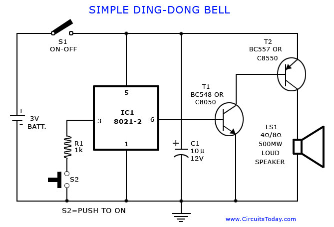
A tone generator circuit, which can be used to create a simple calling bell circuit, is illustrated here. It is constructed using the 8021 integrated circuit (IC), which includes built-in circuitry for producing a "ding-dong" sound. The tone generator circuit...

This circuit employs two balanced modulators to generate a Double Sideband (DSB) signal, followed by the reinsertion of a carrier frequency that differs from the original. This alteration leads to distortion of the input signal. While a voice signal...