
Netduino Building the Circuit on a Breadboard
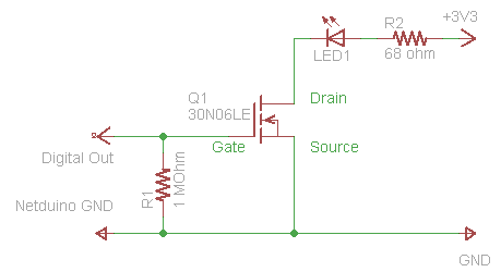
In the circuit schematic, the right half consists of the MOSFET, LED, and a 68-ohm resistor (though a 100-ohm resistor can also be used). The Cathode (-) of the LED connects to the Drain of the MOSFET, while the Anode of the LED connects to one side of the resistor. The other side of the resistor connects to an independent column. The circuit is powered by connecting a red jumper wire from the resistor to the red power rail and a black jumper wire from the Source of the MOSFET to the blue power rail. The left half of the schematic includes the MOSFET, the resistor, and a Netduino. A 1 mega-ohm resistor connects one side to the Gate of the MOSFET and the other side to its own column. Finally, the power supply is connected to the breadboard terminals, with jumper wires leading to the power rails. When the green wire is disconnected and the free end of the yellow wire is briefly touched to the red positive rail, the LED should illuminate but remain on. Reconnecting the gate to ground through the green wire will turn the LED off.
The circuit design utilizes a Power MOSFET as a switch to control the LED's illumination based on the digital signal received from the Netduino. The MOSFET operates by allowing current to flow from the Drain to the Source when a voltage is applied to the Gate. The LED is connected in a manner that the Cathode is linked to the Drain, while the Anode is connected to a resistor, which limits the current flowing through the LED to prevent damage. The choice of a 68-ohm or 100-ohm resistor is sufficient to ensure the LED operates within its safe parameters while providing adequate brightness.
The breadboard's layout is crucial for ensuring that the components are easily accessible and correctly connected. The vertical columns facilitate the arrangement of the MOSFET, resistors, and LED, while the horizontal power rails provide a stable supply of voltage. The intentional break in the power rails allows for modular connections and prevents short circuits. The use of jumper wires enhances flexibility in circuit design, enabling easy adjustments and testing.
When the circuit is powered, the digital signal from the Netduino can be used to toggle the Gate voltage, effectively controlling the MOSFET's conduction state. The observed behavior of the LED turning on when the Gate is briefly connected to the positive rail and remaining on until grounded illustrates the capacitive effects at the Gate terminal. This behavior is typical in MOSFET circuits, where the Gate capacitance retains charge, maintaining the LED's state until a defined discharge path is established. Proper grounding and circuit layout are essential for reliable operation and to prevent unintended behavior.Driving an LED, we covered the electronic theory of how to use a Power MOSFET to turn the LED On and Off via a digital signal. In this post, we are going to walk the reader step-by-step on how to wire-up the circuit on a breadboard.
The Bread board is an electronic designer`s tool for easily prototyping a circuit as it allows easy insertion and removal of wires and components. Yet there is enough friction in each individual socket to hold onto each component reasonably well. The bread board shown below is a pretty common variety. The bread board is broken up into positive (+) and negative (-) power rails (both top and bottom) which span the width of the board. The positive rails are colored in Red, while the negative rails are colored in Blue. It should be noted that the rails are intentionally broken in the middle around column 30. As shown in the picture above, red and black jumper wires connect the two upper rails together. The lower rails shown here are not jumped, so they remain separate. In the middle of the bread board are multiple groups of holes organized in vertical columns and numbered every 5 (for reference).
Each group consists of 5 pin sockets wired together vertically. These groups are not connected over the middle horizontal break of the board, nor do they connect horizontally. Looking at the circuit schematic, we are going to start with the right half of the circuit diagram which consists of the MOSFET, the LED, and the 68 ohm resistor.
(The resistor in the image is a 100 ohm resistor. The value is close enough that the LED will still glow. ) 2) Connect the Cathode (-) of the LED to the Drain on the MOSFET (shown in red labeled D ). You can determine which side of the LED is the Cathode a few different ways: 4) Connect one side of the 68 (or 100) ohm resistor to the Anode of the LED, (shown as column 22) and connect the other side of the resistor to another independent column of holes. (shown as column 29 in the picture. ) 5) Wire the circuit up to the power rails by taking a red jumper wire and connect it from the resistor to the red power rail.
Then take a black jumper wire and connect it from the Source of the MOSFET back to the blue power rail. (shown above. ) Looking up at the circuit diagram again, we are next going to wire up the left half of the schematic which consists of the MOSFET, the resistor, and the Netduino.
6) Take the 1 mega ohm resistor and connect up one side to the Gate on the MOSFET and connect the other side of the resistor up to its own column. (shown in yellow and green. ) 10) Lastly, wire up your power supply to the terminals on the bread board and run jumper wires to the power rails.
As shown here, the red battery pack wire leads to the red terminal which is jumpered by a red wire to the red power rail. Similarly, black to black to black to blue. If you disconnect one end of the green wire and then briefly touch the free end of the yellow wire to the red positive rail, the LED should go on, but not turn off.
As we explained previously, this is because there is no route to ground for the tiny capacitance in the gate. By reconnecting the gate to the ground (through the green wire), the LED should turn off again. 🔗 External reference
Related Circuits
In certain locations near the reservoir or well, when the water level is constrained by the water towers, there is a need for simultaneous monitoring of the water towers and reservoirs as part of an automatic water control system....
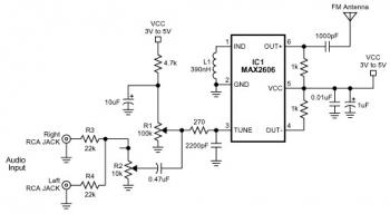
The FM transmitter circuit is built using a single MAX2606 chip. This simple FM transmitter connects a home entertainment system to a portable radio, allowing music to be played in one room and listened to in another, such as...
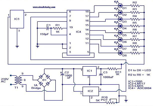
A digital temperature sensor circuit is explained with a circuit diagram. ICs ADC 0804, LM35, and LM317 are used in this digital circuit project. The digital temperature sensor circuit utilizes three primary integrated circuits (ICs): the ADC 0804, LM35, and...
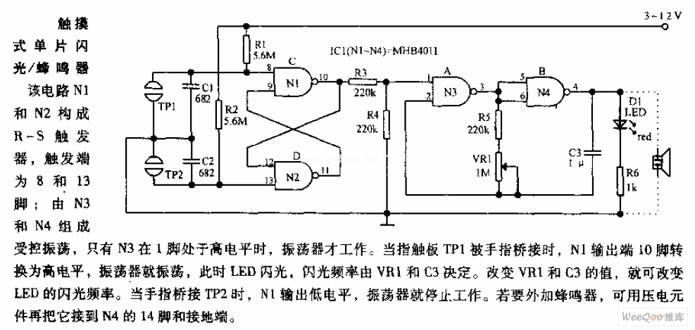
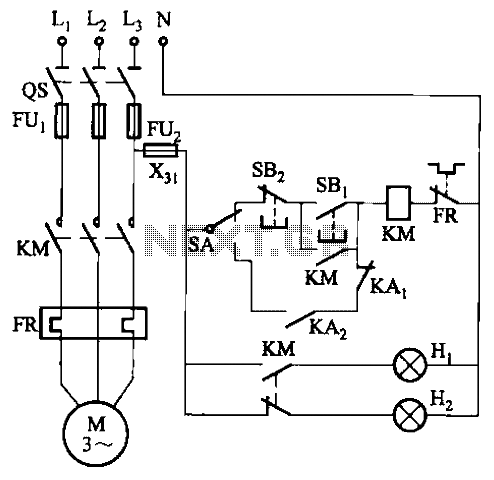
In the circuit, N1 and N2 form the RS flip-flop, with the trigger inputs located at pins 8 and 13. N3 and N4 create a controlled oscillator that operates only when pin 1 of N3 is high. When the...
The circuit can be constructed using a pair of twin-T oscillators, with the Q factor adjusted to the threshold of oscillation, allowing them to resonate like a bell when activated by a voltage pulse. Each twin-T oscillator is designated...
This time, we will share information about Yo3dac's homebrew RF circuit design ideas, including the latest updates from Onmilwiki. Yo3dac is known for innovative approaches in the realm of radio frequency (RF) circuit design, particularly within the homebrew community. The...