
Microcontroller Based Accelerometer
The microcontroller-based accelerometer project utilizes an accelerometer sensor to detect changes in velocity and orientation. This project typically involves interfacing an accelerometer with a microcontroller, such as an Arduino or a PIC, to process the sensor's output signals. The accelerometer measures acceleration in one or more axes, providing data that can be used for various applications, including motion detection, tilt sensing, and gesture recognition.
In a typical setup, the accelerometer is connected to the microcontroller through I2C or SPI communication protocols, allowing for efficient data transfer. The microcontroller's firmware is programmed to read the sensor data, which is then processed to determine the acceleration values. These values can be displayed on an LCD screen, sent to a computer for analysis, or used to trigger other electronic components based on specific conditions.
Power management is also a key consideration in this project. The circuit may include voltage regulators to ensure that both the accelerometer and the microcontroller operate within their specified voltage ranges. Additionally, filtering capacitors can be employed to smooth out any noise in the power supply, which is crucial for accurate sensor readings.
Overall, this project demonstrates the integration of sensors and microcontrollers, providing valuable insights into movement and orientation, with potential applications in robotics, gaming, and mobile devices.Microcontroller Based Accelerometer Project. Just as a speedometer is a meter that measures speed, an accelerometer is a meter that measures acceleration 🔗 External reference
Related Circuits
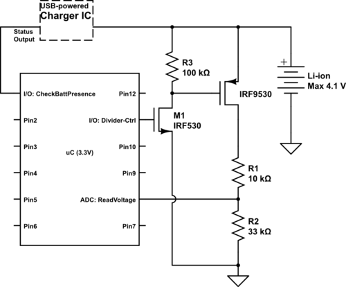
Currently using the PIC24FJ128GA010, there is a plan to utilize an Input/Output port to connect a 4.2 V LiPo battery and monitor the voltage to ensure it does not drop below 3.7 V. It is advised to avoid digital...
This project automates home appliances via a Bluetooth-enabled PC. A USB Bluetooth adapter is utilized on the PC side, while a Serial Bluetooth module is employed for communication. This project involves the integration of a Bluetooth-enabled PC with home appliances...
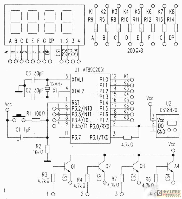
This project utilizes a USB port for power supply, employs a DS18B20 temperature sensor for data acquisition, and is controlled by an AT89C2051 microcontroller. A common anode quad-digit seven-segment display is used for output, allowing for temperature measurement visualization....

A bidirectional H-bridge DC motor control circuit is illustrated. The circuit utilizes the L298 integrated circuit from ST Microelectronics. The L298 is a dual full-bridge driver that supports a wide operating voltage range and can manage load currents up...
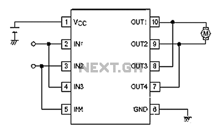
A simple motor control project for forward and backward drive can be implemented using the LB1948M motor driver IC, which features two channels for motor control. The LB1948M is an ideal choice for 12V motor drive systems and can...
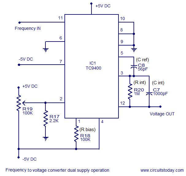
A simple frequency to voltage converter circuit designed around the TC9400 F to V / V to F converter IC. Dual and single supply versions are provided. The TC9400 is a versatile integrated circuit that converts frequency signals into corresponding...
Warning: include(partials/cookie-banner.php): Failed to open stream: Permission denied in /var/www/html/nextgr/view-circuit.php on line 713
Warning: include(): Failed opening 'partials/cookie-banner.php' for inclusion (include_path='.:/usr/share/php') in /var/www/html/nextgr/view-circuit.php on line 713