
microcontroller How can I measure battery voltage with my MCU

The proposed circuit involves connecting a 4.2 V lithium polymer (LiPo) battery to the PIC24FJ128GA010 microcontroller, which will be responsible for monitoring the battery voltage. The monitoring can be achieved through either an Analog-to-Digital Converter (ADC) or an analog comparator. The ADC option allows for precise voltage readings, but since the requirement is simply to check if the voltage drops below a certain threshold, the analog comparator is the more efficient choice.
In this configuration, the analog comparator will continuously compare the voltage of the LiPo battery against a reference voltage set at 3.7 V. The reference voltage can be generated using a voltage divider or a dedicated reference IC to ensure accuracy. When the battery voltage falls below 3.7 V, the output of the comparator will change state, indicating that the battery is nearing its discharge limit.
To implement this circuit, the following components are necessary:
1. **PIC24FJ128GA010 Microcontroller**: This serves as the main control unit for processing signals and executing logic based on the comparator output.
2. **Analog Comparator**: Integrated into the microcontroller, this component will compare the battery voltage to the reference voltage.
3. **Voltage Reference**: A stable voltage reference or a resistor divider network to provide the 3.7 V reference level.
4. **LiPo Battery (4.2 V)**: The power source for the circuit.
5. **Resistors**: If using a voltage divider for the reference voltage, appropriate resistors will be needed to set the desired voltage.
The output of the comparator can be connected to a GPIO pin on the PIC24FJ128GA010, allowing the microcontroller to take action when the battery voltage drops below the specified threshold, such as triggering an alert or shutting down the system to prevent damage to the battery. This simple yet effective monitoring solution ensures the longevity and safety of the LiPo battery throughout its discharge cycle.Currently using the PIC24FJ128GA010 and I am planning to use Input/Output port to connect my 4. 2 V LiPo battery and to check if the voltage value doesn`t go below 3. 7 V. You should avoid digital. You have two options, use an ADC or use an Analog comparator. The last on one should be preferable if you only need to check if the voltage dropped bellow your threshold. Bruno Ferreira Sep 3 `12 at 15:22 @Mattew: Why 3. 7V If you stop at 3. 7V on the discharge curve, you`d be stopping after having used less than 50% of a LiPo`s capacity (depending on your current draw). See discharge curves for a Sanyo Li-ion battery 🔗 External reference
Related Circuits
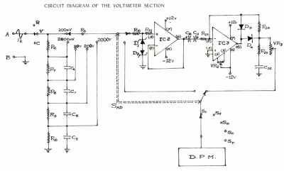
In circuit diagrams provided in equipment manuals, voltages at various points in the circuit are typically indicated. A deviation from these specified values suggests that a component has failed and can help in identifying faulty areas. Specifications include: D.C....
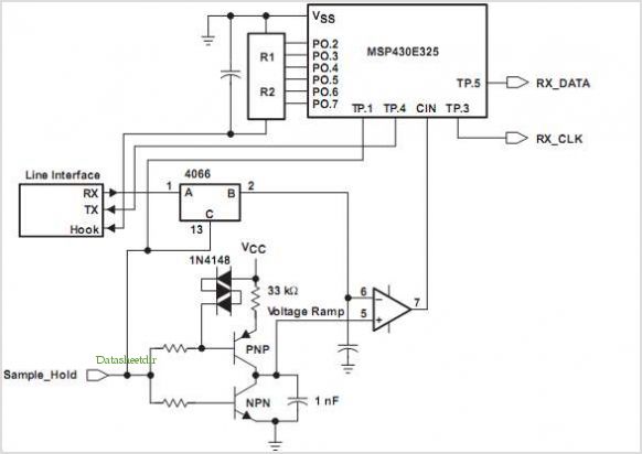
The FX919A is a CMOS integrated circuit that includes all necessary baseband signal processing and Medium Access Control (MAC) protocol functions for a high-performance 4-level Frequency Shift Keying (FSK) Wireless Packet Data Modem. It interfaces with the modem host...
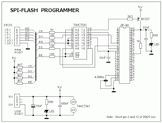
This ISP programmer can be utilized for in-system programming or as a standalone SPI programmer for Atmel ISP programmable devices. The programming interface is compatible with STK200 ISP programmer hardware, allowing users of STK200 to employ the software, which...
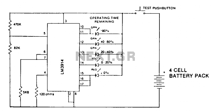
A state-of-charge indication of a sloping-voltage discharge can be utilized as a state-of-charge indicator. A typical voltage comparator circuit that provides a visual indication of the state of charge is presented. Components identified are for a 4-cell input voltage...
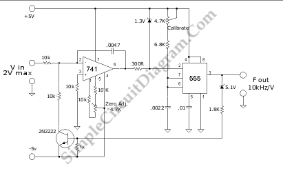
A voltage-to-frequency converter (VFC) circuit is illustrated in the schematic diagram below. The circuit utilizes a 555 integrated circuit (IC) as the central component of its operation. The voltage-to-frequency converter (VFC) is a crucial electronic circuit that converts an input...
This battery charger circuit is regulated and adjustable, enabling it to charge most NiCAD batteries. It is suitable for single cells or multiple battery cells connected in series or parallel configurations. The maximum... This battery charger circuit is designed to...