
Microcontroller Verification Password system
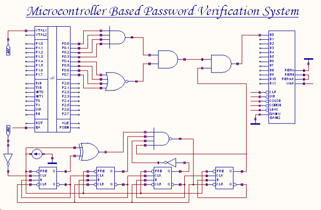
The described system utilizes an 8-bit password verification mechanism, which is fundamental in various security applications. The microcontroller plays a crucial role in this process, as it stores the actual password and executes the comparison logic. Upon receiving the user input, the microcontroller reads the 8-bit password and compares it against the stored password value using a binary comparison algorithm.
The comparison process involves checking each of the 8 bits of the entered password against the corresponding bits of the stored password. If all bits match, the microcontroller generates an 8-bit output signal indicating a successful verification. This output is connected to a logic circuit designed to interpret the result of the comparison.
The logic circuit may consist of basic logic gates such as AND, OR, and NOT gates, configured to produce a high output signal when the comparison result is positive. Specifically, if the output from the microcontroller indicates that the user-entered password matches the stored password, the logic circuit outputs a high signal, which can then be used to trigger subsequent actions, such as unlocking a device or granting access to a secure system.
In summary, this circuit design not only emphasizes the importance of secure password handling but also illustrates the integration of microcontroller functionalities with basic logic circuitry to achieve reliable password verification.An 8-bit password is the input to this system. The password entered by the user is compared with the actual password (password set in the microcontroller using the microprogram) by the microcontroller. The result of the comparison process is an 8-bit output at the output port, which is fed to a logic circuit.
If the user-password is correct, the o utput of the logic circuit will be high. 🔗 External reference
Related Circuits
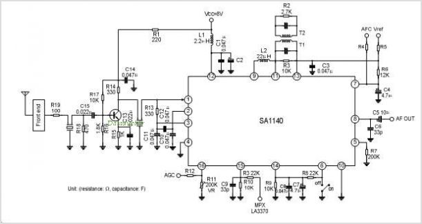
The SA1691 is a monolithic integrated circuit designed for radio cassette tape recorders, clock radios, and headphone radios. This IC includes all functions from the antenna to the audio power amplifier of AM/FM radio, produced by Silan. The SA1691 integrated...
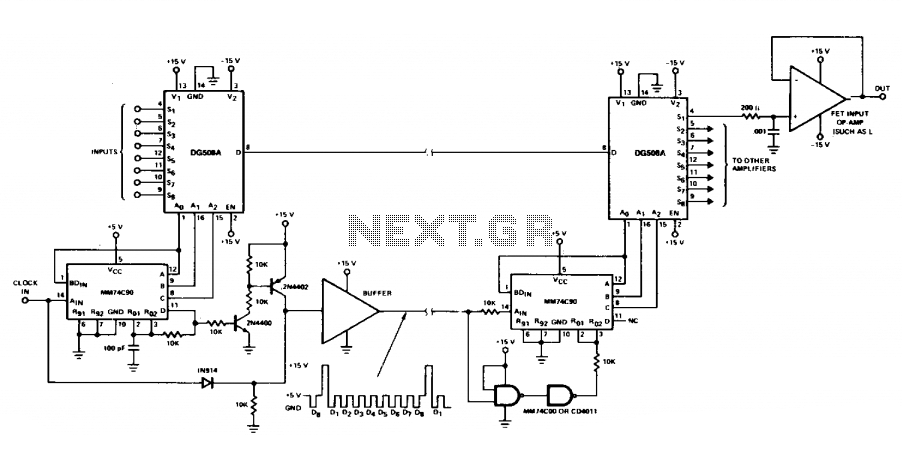
Multiple signals can be transmitted between two locations at the same time by making a minor adjustment to the receiver circuit. An additional DG508A is employed as a demultiplexer, enabling continuous monitoring of all 8 channels. To implement a system...
A circuit is being designed to drive a 4x7 segment display using a PIC microcontroller. The previous implementation utilized four pins to control each of the four digits individually, with a sequential activation method. The designer aims to simplify...
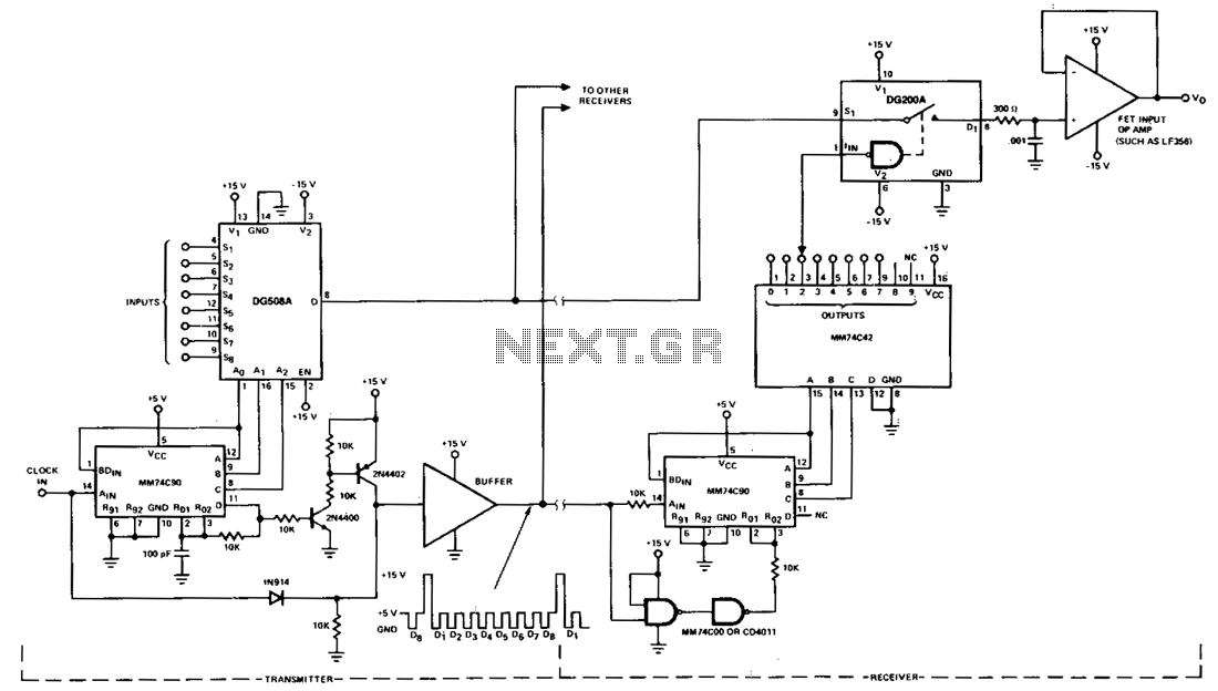
This circuit illustrates a typical multiplex system designed to transmit one of eight inputs to a remote location. A 5-V pulse train is transmitted through a separate channel to execute timing and synchronization functions. A 15-V reset pulse is...

The circuit consists of a small PIC microcontroller, assembly program, and a few other parts to detect a switch closure from an open door, window, or manual push button and then dial the cell phone number, and transmit a...

The FX919A is a CMOS integrated circuit that includes all necessary baseband signal processing and Medium Access Control (MAC) protocol functions for a high-performance 4-level Frequency Shift Keying (FSK) Wireless Packet Data Modem. It interfaces with the modem host...
Warning: include(partials/cookie-banner.php): Failed to open stream: Permission denied in /var/www/html/nextgr/view-circuit.php on line 713
Warning: include(): Failed opening 'partials/cookie-banner.php' for inclusion (include_path='.:/usr/share/php') in /var/www/html/nextgr/view-circuit.php on line 713