
microcontroller driving 4x7 segment display pic 2
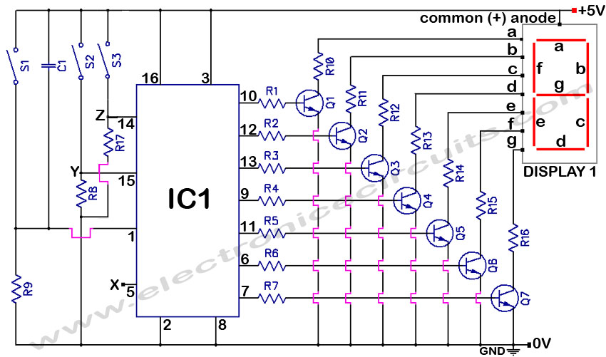
The circuit design involves a 4x7 segment display driven by a PIC microcontroller, where efficient pin usage and space constraints are critical considerations. The primary method of control involves multiplexing, where each digit is activated in sequence to display the desired numbers. The use of a single pin to generate a pulse can be achieved through interfacing electronics, which will manage the toggling of four output pins in a controlled sequence. This approach minimizes the number of pins required from the PIC, enhancing the overall efficiency of the design.
The integration of a 4511 BCD-7 segment driver chip is advantageous due to its capability to handle higher currents, making it suitable for driving the segments without the need for extensive additional circuitry. This chip simplifies the design by reducing the number of direct connections to the PIC, allowing for a more compact layout.
Alternatively, the implementation of an 8-bit shift register, such as the 74HC595, provides another method for controlling the segments. This configuration allows for serial data input, effectively managing the eight segments while using only six pins. The common cathode or anode can be controlled via a transistor, ensuring that the segments illuminate correctly based on the data received from the shift register.
In scenarios where board space is a constraint, Charlieplexing presents a viable solution, requiring only eight pins to control the display while achieving similar brightness and performance levels to direct driving methods. However, the complexity of the wiring must be carefully planned to avoid confusion during assembly.
The previous project using NPN transistors to switch digits on and off demonstrated a practical application of direct control, with resistors used to limit current to the segments. The PIC16F88 microcontroller was effective in managing the overall current consumption, which was measured at approximately 70mA, inclusive of additional components on the board.
The exploration of directly driving LED segments from the PIC using PWM techniques raises important considerations regarding the microcontroller's current specifications. While some projects have successfully operated without resistors, it is vital to ensure that the total current remains within safe operating limits to prevent damage to the microcontroller.
In summary, the design of a circuit to drive a 4x7 segment display using a PIC microcontroller can be approached through various methods, including multiplexing, the use of dedicated driver chips, shift registers, and Charlieplexing. Each method has its advantages and challenges, particularly concerning pin usage, board space, and current management. Careful consideration of these factors will lead to an effective and efficient design.I`m designing a circuit to drive a 4x7 segment display using a PIC. I`ve done this in the past without any drama. I would just use four pins to control each of the four digits (one each). I`d switch one digit on, wait a bit, turn it off, then switch the second digit on etc. I was hoping that I could get away with using just one pin from the PIC an d pulse it (square wave) through some interfacing electronics which would have four output pins that toggle on and off in a sequence, one at a time. (IE 1, 2, 3, 4, 1, 2, 3, 4 etc) Or even better a 4511 BCD-7 segment driver chip, that even has high current capacity to feed the display - it`s often used commercially to save pins when multiplexing 7 segment displays.
Another option to consider is to use an 8-bit shift register (like the 74HC595) to connect to the 8 segments, and drive the common cathode/anode pin using a transistor. This will require 6 pins, 3 for the shift register and 4 for the digits. If board space is tight and you don`t have room for an extra chip, you might consider Charlieplexing the display.
The "up side" is you only need eight (8) pins and you should get the same brightness and performance you`re getting now (with direct segment drive). The "down side" is the funky display wiring. The last project I used a 4x7seg display and switched each digit on/off with NPN transistors and drove each segment directly (via resistors) from the PIC.
On a side note, I used PIC16F88. See image below. This is an older one I did some time ago. As you can see, the board`s getting pretty cramped. Although I was fairly happy with the current usage (overall about 70mA including running the sensor on the board). And it was quite an effective little unit. It`s a small display. Actually, the board size limitations are a mere 20x45mm! This is just about enough space to fit the 3x7seg display, plus a PIC16F88 (SOIC package). Adding another PIC would be great, although I`m not sure I`d have enough board space to accommodate both PICs.
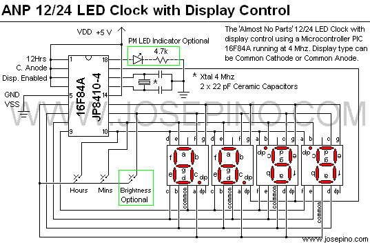
I like the idea of the 74HC595 though. Looks very compact. Another question - I`ve seen some projects where the LED/segments have been driven directly from the PIC (with no resistors) and reduced using PWM. If the overall current consumption is within the PIC`s limitations, is this ok to do Or should I just steer clear from this method altogether Just take a look at this link I made this clock 18 months ago it has NO resistors unless you count the one for the AM/PM led if used, and has been running faultlessly ever since.
Jose`s use of charlieplexing is the key to size and component numbers and as said earlier in this thread the only downside is the strange segment wiring, but it definately works well and saves space and components. My build is just slightly bigger than the 4 LED displays I used but that was with TTH PIC and not SMT that you are using, just imagine how small yours could be!
🔗 External reference
Related Circuits
This resource provides a variety of PIC Microcontroller tutorials that cater to both beginners and advanced users. These tutorials enable individuals to gain expertise in microcontroller programming and circuit design without the need for costly embedded system courses. The tutorials...

This circuit diagram of a digital clock utilizes six common anode seven-segment displays to indicate the time. It does not require microcontrollers or PICs for operation. The circuit operates using the MM5314 integrated circuit, functioning at either 50 Hz...
A voltmeter and ammeter using a PIC microcontroller can measure voltage and current simultaneously. This setup employs a PIC16F876A as the data processor for voltage and current measurements. An LCD display (16x2) is utilized to present the measured voltage...
A circuit diagram and sample code is provided to read and write to the 74LC16B memory from a PICAXE microcontroller. The circuit involves interfacing a PICAXE microcontroller with a 74LC16B memory chip, which is a type of EEPROM (Electrically Erasable...

This project involves a straightforward data logger utilizing the PIC12F683 microcontroller. The microcontroller periodically reads temperature values from a temperature sensor and stores these readings in its internal EEPROM memory. The circuit design for this data logger project incorporates several...
4033 7 Segment Common Anode Display Event Counter Circuit. This circuit can count from 0 to 9 with a reset function and a display test feature. The 4033 7-segment common anode display event counter circuit is designed to count events...
Warning: include(partials/cookie-banner.php): Failed to open stream: Permission denied in /var/www/html/nextgr/view-circuit.php on line 713
Warning: include(): Failed opening 'partials/cookie-banner.php' for inclusion (include_path='.:/usr/share/php') in /var/www/html/nextgr/view-circuit.php on line 713