
Microphone Preamplifier BC547B
This microphone preamplifier circuit is designed to interface dynamic and electret microphones with standard line-level audio inputs, making it suitable for various applications, including home audio systems and computer sound cards. The circuit employs a single transistor amplifier configuration to achieve a gain of approximately 30-40 dB, which can vary based on transistor characteristics, temperature, and supply voltage.
The design incorporates several key components: a 9V battery serves as the power source, consuming less than 10 mA, ensuring energy efficiency. The presence of an LED (D1) provides visual feedback that the circuit is powered and operational. The voltage drop across the LED, approximately 1.8V for a red LED, is accounted for in the circuit design to ensure proper biasing of the transistor (Q1).
Capacitors (C1, C2, C3) are strategically placed to block DC bias from the microphone inputs, allowing only AC signals to pass through to the transistor's base. Additionally, a filter composed of resistor R4 and capacitor C5 mitigates potential noise from the power supply, enhancing the overall sound quality of the output signal.
For the electret microphone input, resistor R1 is included to provide the necessary bias current, typically around 1 mA, required for the operation of the electret capsule's internal amplifier. The circuit is designed to accommodate typical low-cost electret microphones available in the market.
The physical construction of the circuit is recommended to be housed in a small metal enclosure, which aids in reducing external electromagnetic interference and noise. The enclosure should also accommodate the 9V battery, ensuring a compact and portable design. Input connectors consist of a 6.3 mm jack for dynamic microphones and a 3.5 mm mono jack for electret microphones, both accessible from the front panel, along with the LED indicator and power switch, facilitating ease of use.
This preamplifier circuit is characterized by its simplicity and effectiveness for casual audio applications, providing a reliable solution for interfacing microphones with audio equipment.This is a simple microphone preamplifier circuit which you can use between your microphone and stereo amplifier. This circuit amplifier microphone suitable for use with normal home stereo amplifier line/CD/aux/tape inputs.
This microphone preamplifier can take both dynamic and electret microphone inputs (preamplifier provides power foe electret microphone elements). The idea of this circuit is to keep the design as simple as possible to be easy to build. That was my goal when I needed a simple external microphone preamplifier for my mixer. The performance of the circuit is nothing superior but can be used with many not so serious projects.
Circuit performance: Amplification 35 dB, flat frequency response from 20 Hz to 20 kHz, quite poor distortion performance figures, a little bit noisy Availability of components: Uses common and easily available components Design testing: I have built few microphone preamplifiers based on this circuit and theu have worked without problems. Applications: Interface dynamic or electret microphone to a line level audio input in HIFI amplifier or computer soundcard.
Power supply: 9V battery, takes less than 10 mA current. The circuit is a simple one transistor amplifier with amplification of about 30-40 dB (depends on transitor, temperature and voltage). The dynamic mic input is just a simple one transistor amplifier circuit with nothing special in it. LED D1 is in the circuit to show that the circuit operates. The voltage drop caused by LED (around 1.8V for RED led) has been taten in account when designing the amplifier circuit built around Q1.
Resistor R4 and capacitor C5 make a filter to filter out possible noise from battery or other power source which is used to feed this circuit. Capacitors C1, C2 and C3 are used to block the DC bias on Q1 base to flow out of microphone input to microphone (the polarity of all capactors is straigh line = + and curved line = -).
The circuit is bet to build to a small metal box like in the picture above. Put the 9V battery inside the case too. Battery power and metal box keep external noise and interference sources away. I used standard 6.3 mm jack for dynamic microphone and 3.5 mm mono jack for electret micrphone both installed to from, panel of the metal box. The LED and power switches are also installed to front panel. Electret microphone input has a resistor R1 fo feeding current through electret microphone capsule when it is connected to the electret microphone input.
Electret microphone needs some current (about 1 mA) flowing through it to operate, because there is a small amplifier circuit inside the microphone capsule. This circuit is suitable for all typical cheap electret capsules which available from any electronic component shop.
Because electret microphones have higher signal level output, it is quite easy to overdrive the amplifier when you shout to electret microphone. 🔗 External reference
Related Circuits
Although many album titles that were once available on vinyl are gradually being released on CDs, not all titles are accessible. It is possible that there are valuable records in a collection that one might wish to convert to...
The computer needs at least 180 millivolts peak-to-peak and the condenser microphone in my headset produces about 20 millivolts peak-to-peak into a 2.2k load with normal speech levels. There are USB ports on the machines, so I can use...
This unit would be mounted in a small plastic or preferably metal box, with a 9V battery, level control, a male XLR connector (same as on a mic) and a switch. Current drain is low, since the circuit only...
This is the basic FM transmitter that I built. In theory, according to electronics, it shouldn't work but works fine and is very sensitive. It can transmit the signal up to 45 yards (about 40 meters). A sensitive FM...
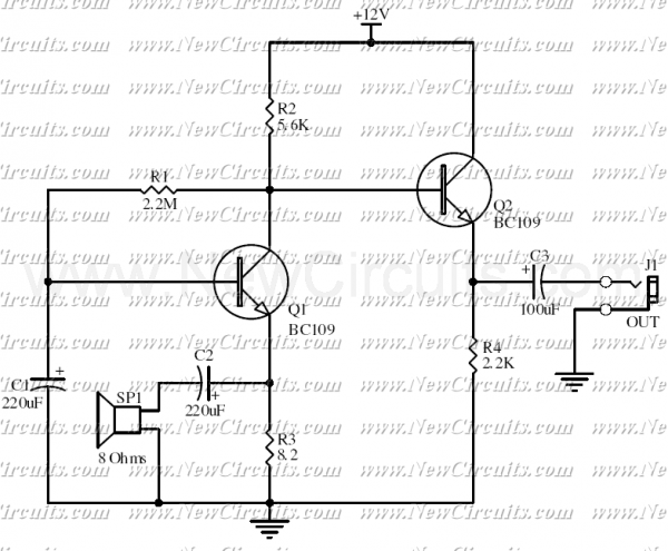
This circuit allows you to use a cheap loudspeaker as a microphone. Sound waves reaching the speaker cone cause fluctuations in the voice coil. The voice coil moving in the speaker's magnetic field will produce a small electrical signal. The...
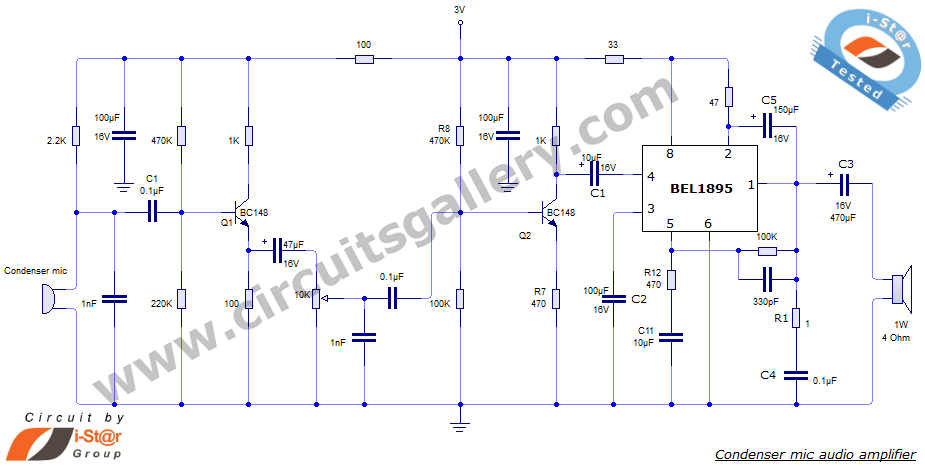
This document presents an audio amplifier circuit suitable for use in walkie-talkies, low-power transmitters, and packet radio receivers. The circuit utilizes a condenser microphone audio amplifier that delivers high-quality audio output of 0.5 watts at 3 volts. The design...
Warning: include(partials/cookie-banner.php): Failed to open stream: Permission denied in /var/www/html/nextgr/view-circuit.php on line 713
Warning: include(): Failed opening 'partials/cookie-banner.php' for inclusion (include_path='.:/usr/share/php') in /var/www/html/nextgr/view-circuit.php on line 713