
Microphone FM bug transmitter
This FM transmitter circuit operates within the FM radio frequency band, typically from 88 MHz to 108 MHz. The design relies on a simple oscillator circuit that generates the radio frequency signal, which is then modulated by audio input, such as from a microphone. The primary components of the circuit include a transistor, which acts as the amplifier and oscillator, and a coil, which is crucial for frequency selection.
The coil, made from 24 AWG wire, consists of five turns with a diameter of approximately one centimeter. This configuration allows for the desired frequency range to be achieved by adjusting the coil's dimensions. The inductance of the coil, in conjunction with the capacitance in the circuit, determines the resonant frequency. Since variable capacitors are not readily available, the coil serves as the primary means of tuning the frequency. Adjusting the spacing of the coil turns can effectively alter the inductance, allowing for fine-tuning of the transmitter frequency.
To construct the circuit, a breadboard can be utilized for easy assembly and testing before soldering the components onto a more permanent board. This approach allows for troubleshooting and adjustments without permanent modifications. After confirming that the circuit functions as intended, securing the coil with hot glue is recommended to maintain the frequency stability.
It is essential to note that the transmitter's range may vary based on environmental factors and the sensitivity of the receiving FM radio. The transmitter should be operated away from water and metallic objects to prevent interference with the frequency stability. This circuit serves primarily as an educational project, demonstrating fundamental concepts of radio frequency transmission and modulation.This is the basic fm trasmitter that I built. In theory, according to electronics, it shouldn't work but works fine and is very sensitive. It can transmit the signal up to 45 yards (about 40 meters) . A sensitive FM radio can pick up the signal up to 100 yards (80 meters) but I can't see any reason for it. This kind of microphones are also called "spy microphones" but knowing that the battery is bigger than the actual circuit, I can't see any application like that, anyway, this circuit should be used as educational application only.
It doesn't have special parts and the frecuency is selected by the coil. The coil is a 24 AWG wire, it have 5 loops with a diameter of one centimeter. It can be easily build using a pencil. Here is the circuit assembled in the construction board. This circuit can be tested without problem before soldering the parts. This is a photo taken I was testing the circuit. After the circuit was tested and verified that works, I build my FM transmitter Now, the last step, is to adjust the frecuency. With a toothpick you can make wider or narrow the coil until the frecuency is between 89 Mhz to 104 Mhz.
It takes a while to setup and tune up, but is not too hard to make it work. As variable capacitors are not easy to buy, the solution is to choose the frecuency with the coil. Once it is tuned, hot glue can be used to keep the coil fixed, so the frecuency will not change. This microphone cannot be used close to water, the body or near metals because it may cause the frecuency to change.
Related Circuits
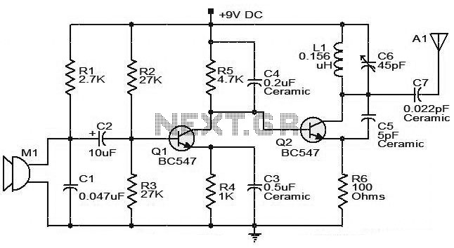
The moderate power FM transmitter circuit employs two transistors. The voice signals picked up by the microphone will be amplified by the transistor. The described FM transmitter circuit utilizes two transistors to facilitate the modulation and amplification of audio signals....

The following diagram is the schematic diagram of a four-transistor FM transmitter circuit designed by Paul K. Sherby. Components List: R1, R2, R8 = 1K, R3 = 100K, R4 = 150K, R5, R7 = 10K, R6 = 220 ohm,...
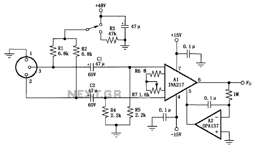
The circuit depicted in the figure consists of an INA217 professional miniature microphone preamplifier. A switch is included to select the use of phantom power. When the switch is connected to +48V, phantom power is enabled; if the switch...
My FM Wireless Microphone has been a very popular project with beginners and experienced constructors alike. It has been used inside guitars and as the basis of a remote control system. I do however, receive many requests for a...
Crystal 80mW FM transmitter circuit diagram of the production The Crystal 80mW FM transmitter circuit is designed to generate frequency modulated (FM) signals suitable for short-range audio transmission. This circuit primarily consists of a crystal oscillator, which serves as...
This low-power video transmitter is designed for remote control (R/C) applications, surveillance, or amateur radio purposes. It utilizes seven transistors within a crystal oscillator-multiplier RF power amplifier chain, along with a high-level video modulator. A supply voltage of 9...