
Microphone Voice-Over Circuit
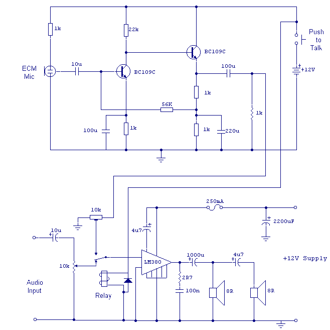
The voice-over unit described is an essential component in audio communication systems, designed to prioritize microphone input over other audio signals when activated. The core of the unit consists of a microphone connected to a preamplifier, which boosts the microphone's signal before it reaches the main amplifier. This preamplifier is crucial for ensuring that the microphone can operate effectively even when placed at a distance from the main amplification system.
The preamplifier circuit utilizes two BC109C transistors, a widely used NPN transistor known for its low noise and high gain characteristics. The first BC109C transistor is configured in a common emitter mode, which is effective for providing high voltage gain. This configuration allows the microphone's low-level audio signal to be amplified significantly. The second BC109C transistor is configured as an emitter follower, which serves to buffer the output of the common emitter stage. This configuration provides a low output impedance, making it ideal for driving subsequent stages of the circuit, such as the LM380 amplifier.
The change-over switch in this design is implemented using a relay with a single changeover contact, which allows for seamless switching between the microphone input and the amplifier's audio signal. When the "push-to-talk" switch is activated, the relay engages, routing the microphone signal to the amplifier while muting other audio inputs. This functionality is critical in environments where clear and prioritized communication is necessary, such as in broadcasting or public speaking scenarios.
The LM380 amplifier serves as the final amplification stage in this circuit, capable of driving speakers or other audio outputs. It is designed to handle significant power levels, making it suitable for a wide range of applications. The overall design requires three wires to connect the remote microphone unit to the amplifier and switching unit, simplifying installation and ensuring reliable operation.
This voice-over unit schematic provides a robust solution for audio applications requiring prioritized microphone input, leveraging the advantages of transistor amplification and relay switching to achieve high-quality audio performance.In its simplest form, a voice-over unit is just a microphone and change-over switch feeding an amplifier, the output from the microphone having priority over the amplifiers audio signal when the "push-to-talk" switch is pressed. In this circuit, a preamplifier immediately follows the microphone and is designed to be used some distance away from the main amplifier.
The changeover switch is nothing more than a relay with a single changeover contact. For completion, an amplifier based on the LM380 is shown. Three wires are needed to connect the remote microphone unit to the amplifier and switching unit. With reference to the above schematic, the two BC109C transistors are used to make a microphone preamplifier. The left hand BC109C operates in common emitter mode, the right hand emitter follower. The combination form a high gain, low output impedance amp 🔗 External reference
Related Circuits
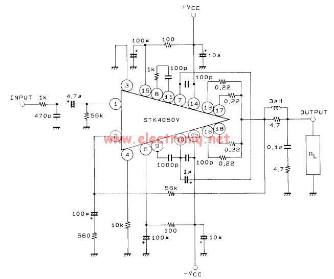
This 200-watt audio amplifier circuit diagram is based on the STK4050V high-power audio amplifier IC, designed to deliver up to 200 watts of audio power on a single channel. The STK4050V 200-watt audio amplifier circuit is pin-compatible with other...
This is a transistor tester integrated into a circuit or printed circuit board (PCB). It is utilized when a project does not function correctly, allowing for the testing of electronic components. The transistor tester is a crucial tool in electronic...
The WPG DM8168 DaVinci high-definition video System on Chip (SoC) offers multiple DVR/NVR surveillance solutions, utilizing the MT9M033 image sensor as a key component in safety monitoring systems. This solution is complemented by Conexant's line of multi-channel video surveillance...
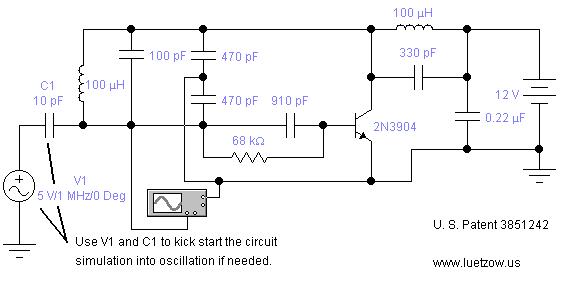
The oscillator circuits presented on this page are derived from expired or non-maintained U.S. Patents. All circuits are formatted for "Electronic Workbench 5.12" or "Multisim 7" circuit simulation software. A note regarding SPICE simulation of electronic oscillator circuits: all...
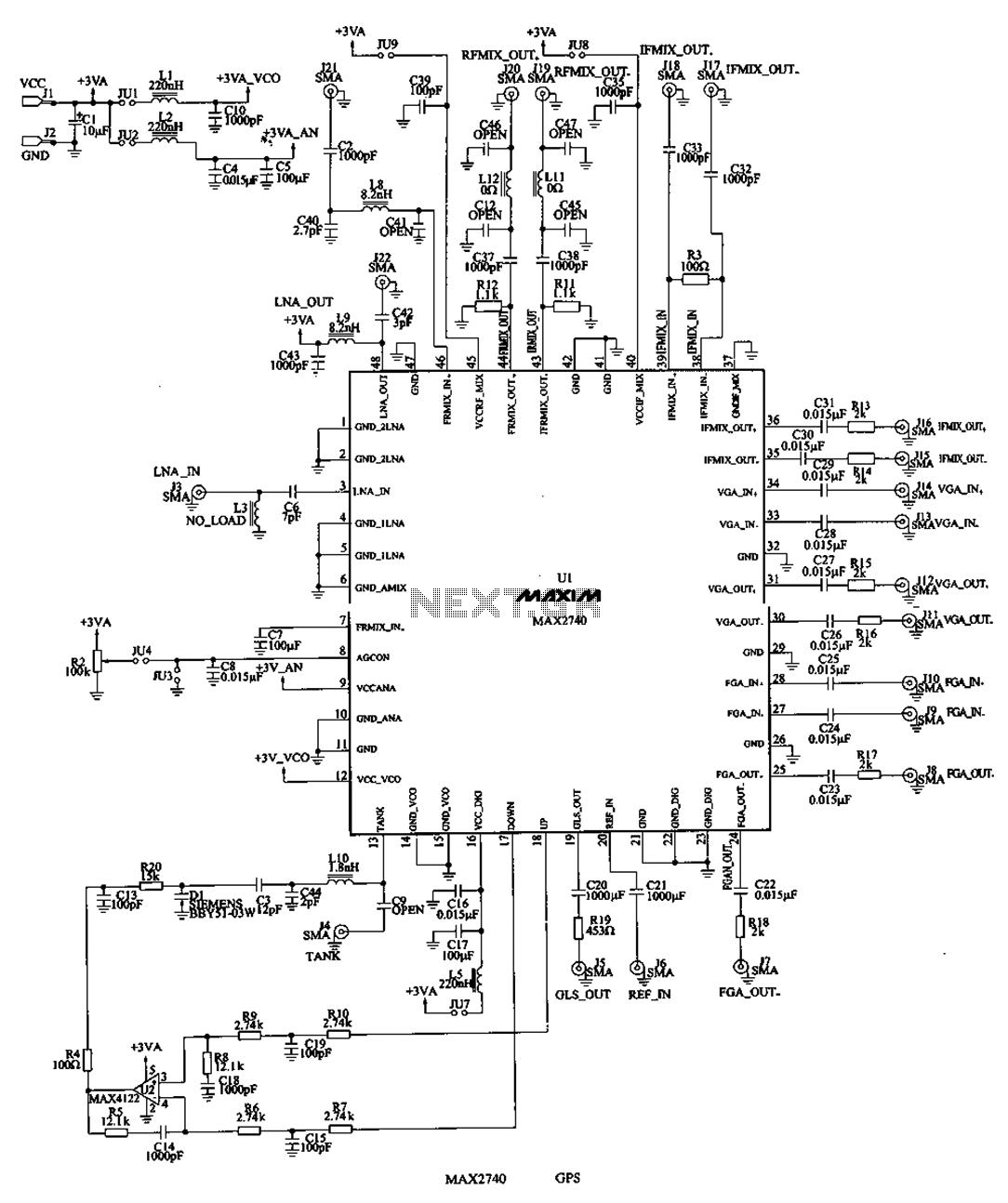
The MAX2740 is a complete GPS receiver down converter chip that processes the signal from the antenna to the input of digital signal processing. The receiver channel of the MAX2740 includes a low-noise amplifier (LNA), a downconverter, a variable...
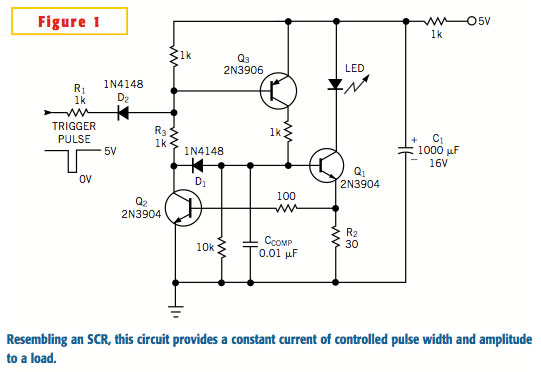
A typical silicon-controlled rectifier (SCR) requires a trigger current to latch on. Once the device is latched, the current flowing through the SCR is determined only by the external component values. The SCR lacks the ability to limit current...