
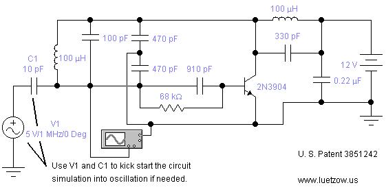
Inductive Electronic Oscillator Circuit
The provided oscillator circuits utilize various configurations to generate oscillatory signals, which are essential in numerous applications including signal generation, timing, and frequency modulation. The circuits can be analyzed and simulated using Electronic Workbench 5.12 or Multisim 7, both of which are robust platforms for electronic circuit simulation.
In these simulations, users can observe the behavior of the oscillator circuits in real-time, allowing for a thorough understanding of their performance characteristics. The circuits typically consist of active components such as operational amplifiers, transistors, or integrated circuits, along with passive components like resistors, capacitors, and inductors, which together establish the feedback necessary for oscillation.
The selection of position sensing oscillators indicates a focus on circuits that can detect and respond to physical position changes, which can be particularly useful in applications like robotics, automotive systems, and automation technology. As these patents have expired, the circuits can be freely utilized and modified, promoting innovation and development in the field of electronics.
For users experiencing difficulties with oscillation in their simulations, it is advisable to verify component values, connections, and the overall configuration of the circuit. Each simulator may have unique settings or limitations that could affect the circuit's performance. Therefore, consulting the documentation for the specific simulation software being used can provide additional insights into troubleshooting and optimizing circuit behavior.The oscillator circuits presented on this page are from expired or non-maintained U. S. Patents. All circuits are presented in "Electronic Workbench 5. 12" or "Multisim 7 circuit simulation formats". A note on spice simulation of electronic oscillator circuits. All of the oscillator circuits presented on this web page have been simulated using eithe r Electronic Workbench 5. 12 or Multisim 7 electronic spice programs. All of the circuits will oscillate using the simulator schematics as shown. It is unknown if the circuits will oscillate on other brands of spice circuit simulators. If you have problems getting your circuit to oscillate on your simulator, You can to email questions to me at bob@luetzow. us. This web page is basically about electronic oscillator circuits and how to demonstrate the circuit`s oscillating functions using spice software.
The position sensing oscillators were selected because they are all expired patents and are in the public domain. 🔗 External reference
Related Circuits
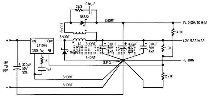
Input voltages can range from 8 V to 30 V. The load range for the 5 V output is from 0.05 A to 5 A, while the load range for the 3.3 V output is from 0.1 A to...
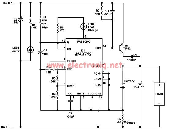
The MAX712 charger requires a power supply with an output voltage that is at least 1.5V higher than the maximum battery voltage. Charge completion is determined by a voltage-slope detecting analog-to-digital converter, a timer, and a temperature window comparator. The...
This discussion covers three different Xenon flashing circuits from disposable cameras. From these circuits, unique techniques not found in any theoretical literature will be presented. The first circuit consists of six building blocks. An old disposable flash camera and...
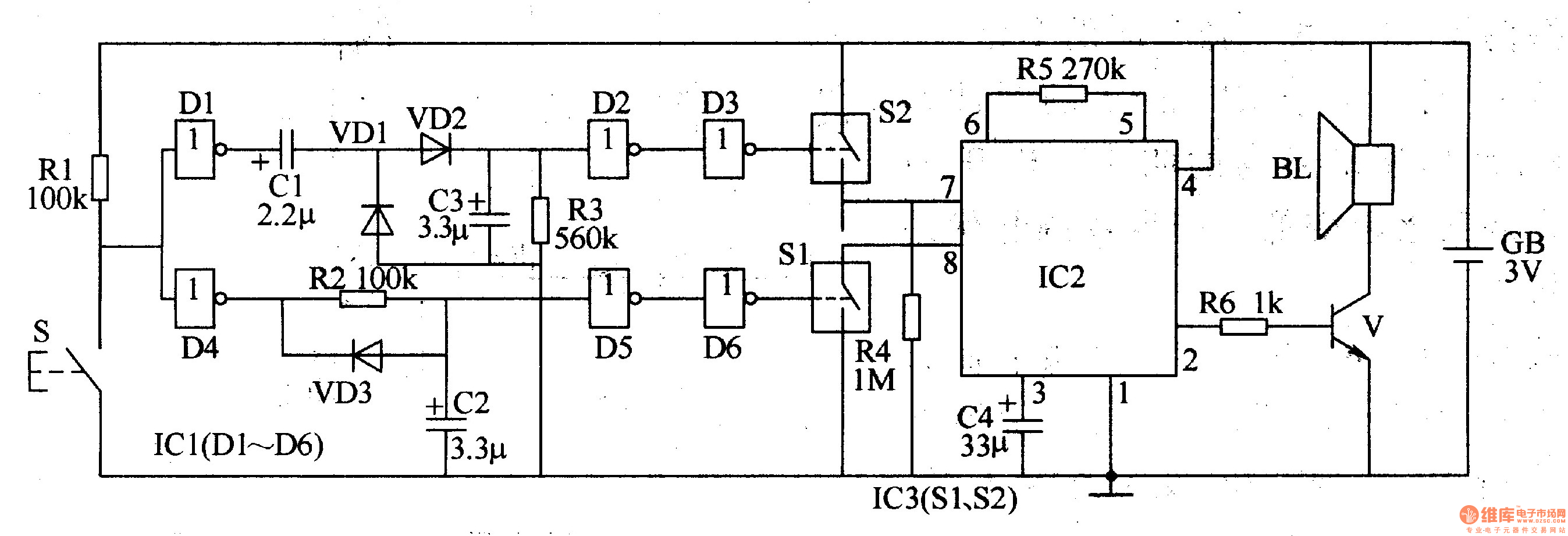
The two-tone electronic doorbell circuit comprises a trigger control circuit and a doorbell generating circuit, as illustrated in Figure 3-108. The trigger control circuit includes a doorbell button (S), resistors (R1-R3), electrical components (C1-C3), diodes (VD1-VD3), six NOT gate...
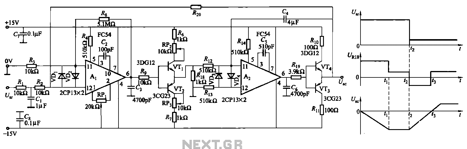
The ZKJ-S-type buffer controller circuit is designed for motor starting slip control. This buffer controller is composed of two operational amplifiers, Ai and Az. The operational amplifier Ai functions as a speed amplifier that saturates, while Az acts as...
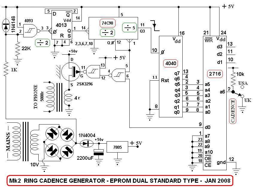
This is a switch-selectable dual output version of a previous design from 2007, utilizing a field-programmed EPROM to generate two versions of the ringing sequence. The AC mains voltage is stepped down to approximately 10 V AC and then...