
MICROPOWER METAL DETECTOR
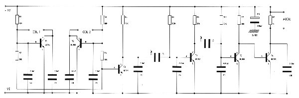
This metal detector circuit effectively employs the 4030 CMOS integrated circuit, which houses four exclusive-OR gates. The configuration of these gates as twin oscillators is crucial for the detection mechanism. The search coil, integral to the design, serves as the inductive element in one oscillator, while the second oscillator operates independently. When metal is detected, the inductive properties of the search coil change, leading to a shift in frequency of the oscillators.
Gates A1 and A2 are tuned to specific frequencies—160 kHz and 161 kHz—creating a very narrow frequency difference that is key to the device's sensitivity. The output pulses from these two oscillators are mixed in gate A3, resulting in a composite signal that includes both the sum and difference frequencies. The primary frequencies of interest are 1 kHz and 321 kHz. To isolate the desired signal, a 10 kHz low-pass filter is employed at A4, which effectively removes the higher frequency component (321 kHz), ensuring that only the 1 kHz signal is amplified.
The amplified 1 kHz signal is then routed to a crystal headset, allowing for auditory feedback to the user. This design enables the metal detector to maintain high sensitivity, capable of detecting small metal objects, such as coins, from a distance of up to one foot. The simplicity of the circuit, combined with the effective use of CMOS technology, contributes to a reliable and efficient metal detection system.This battery-powered metal detector uses four exclusive-OR gates contained in the 4030 CMOS integrated circuit. The gates are wired as a twin-oscillators and a search coil serves as the inductance element in one of the oscillators.
When the coil is brought near metal, the resultant change in its effective inductance changes the oscillator`s freque ncy. Gates A1 and A2 form the two oscillators which are tuned to 160 and 161 kilohertz respectively. The pulses produced by each oscillator are mixed in A3, its output contains sum and difference frequencies at 1 and 321 kHz. The 321 kHz signal is filtered out by the 10 kHz low-pass filter at A4, leaving the 1 kHz signal to be amplified for the crystal headset connected at the output.
The device`s sensitivity is sufficient to detect coinsized objects a foot away. 🔗 External reference
Related Circuits

This smoke detector electronic project is designed using the LM1801 and common electronic components. The smoke detector circuit diagram does not utilize ionization detection, gas sensors, or optocouplers; instead, it employs two photoresistors (LDRs) and an LED. The circuit...
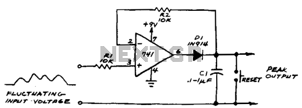
If the subsequent input voltage exceeds that stored in C1, the comparator voltage will go high and charge C1 to the new higher peak voltage. The comparator will charge C1 until the voltage across the capacitor equals the input...
A reasonably effective bifilar oscillator (BFO). Its performance is not comparable to more advanced commercial products, but it still functions adequately. During World War II, metal detectors based on the same principle were utilized by combat engineers from various...

This circuit employs a 15-kHz oscillator coil. When metal is removed from the energy field, the oscillator voltage is rectified and compared to a reference. A decrease in oscillator voltage activates comparator IC2, causing D4 (LED) to turn off. L1...
Variable resistor R1 adjusts the light threshold at which the circuit triggers. R1's value is chosen to match the photocell's resistance at darkness. The circuit uses a CMOS 4001 IC. Gate U1a acts as the trigger, U1b and c...
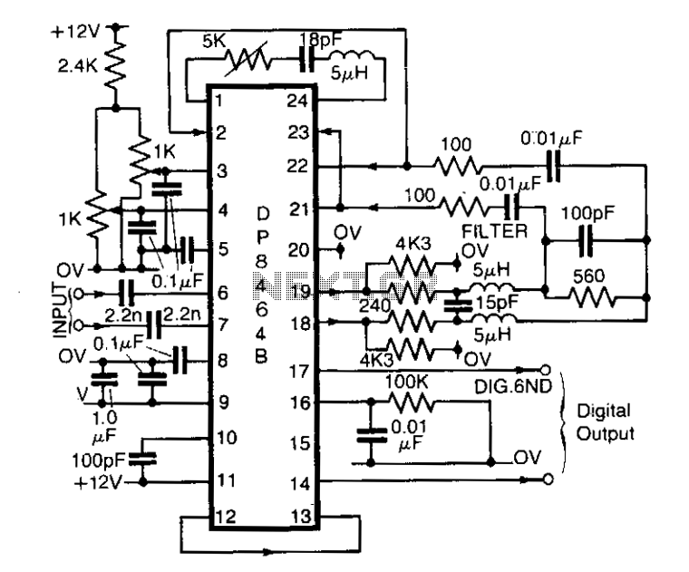
The DP8464B from National Semiconductor is designed primarily for use in disk systems as a pulse detector. However, it can also function effectively as a general-purpose peak detector for analog signals up to 5 MHz. This integrated circuit can...