
Peak detector II
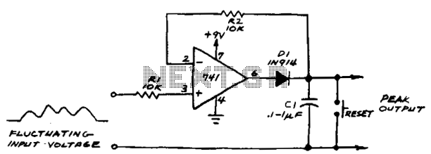
In this circuit, a comparator is utilized to monitor the voltage levels and control the charging of a capacitor, designated as C1. The operational principle hinges on the comparator's ability to compare the voltage across C1 with an incoming voltage signal. When the input voltage surpasses the voltage currently stored in C1, the comparator output transitions to a high state, indicating that the capacitor should be charged.
The charging process involves the comparator actively driving a control signal that connects C1 to a voltage source. This connection allows C1 to accumulate charge until the voltage across its terminals matches the level of the incoming input voltage. The charging mechanism is typically facilitated through a resistor-capacitor (RC) network, which helps regulate the rate at which C1 charges, ensuring that the voltage rise is smooth and controlled.
Once the voltage across C1 equals the input voltage, the comparator output will revert to a low state, effectively stopping the charging process. This behavior establishes a feedback loop that maintains the voltage across C1 at the same level as the input voltage, thus enabling stable operation in applications such as voltage regulation, peak detection, or signal conditioning.
The design considerations for this circuit should include the selection of appropriate values for C1 and any resistors used in conjunction with the comparator, as these components will influence the response time and stability of the circuit. Additionally, the comparator's specifications, such as its input voltage range and output drive capability, must be compatible with the intended application to ensure reliable performance. If subsequent input voltage exceeds that stored in Cl, the comparator voltage will go high and charge Cl to new higher peak voltage. The comparator will charge Cl until the voltage across the capacitor equals the input voltage. 🔗 External reference
Related Circuits
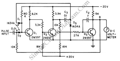
This is a Peak Voltmeter circuit. This circuit can be viewed as a pulse stretcher, which captures fast pulse signals to be measured by a slow response voltmeter. The Peak Voltmeter circuit is designed to accurately measure the peak voltage...
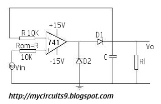
The circuit presented includes resistors of 10k ohms and capacitors of both 1µF and 10µF. There is also a diode included in the schematic. Assistance is requested for corrections to achieve the desired output. The circuit design consists of a...
This project is offered totally free for those who are interested in it. I have tried to make this article as complete as possible, but I will not assume any liability for any errors or omissions in this article....
Detects the presence of a live mains conductor. Minimum parts counting. If the unit is brought close to a live conductor (insulated, and even buried in plaster) capacitive coupling between the live conductor and the probe clocks the counter,...
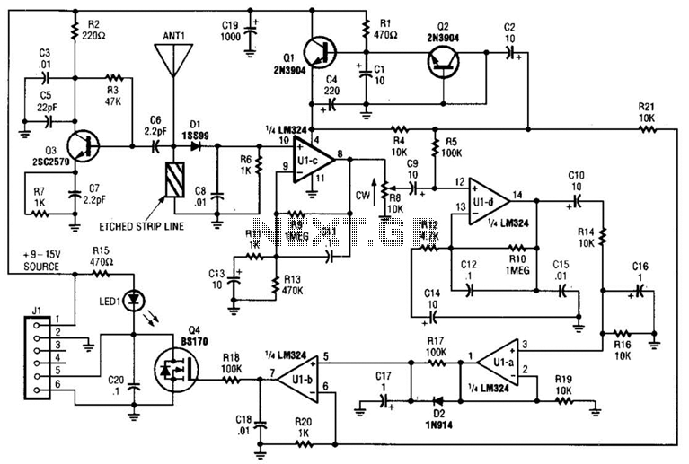
Operating at approximately 1.1 GHz, the detector senses disturbances in the electromagnetic field surrounding the antenna. The Doppler signal generated by detector D1 is amplified and used to control a power MOSFET switch. The antenna consists of a short...
This homemade metal detector circuit is designed to locate objects made of materials with relatively high magnetic permeability. While it may not be sensitive enough for detecting buried coins, it can effectively identify larger metallic treasures. The circuit operates...
Warning: include(partials/cookie-banner.php): Failed to open stream: Permission denied in /var/www/html/nextgr/view-circuit.php on line 713
Warning: include(): Failed opening 'partials/cookie-banner.php' for inclusion (include_path='.:/usr/share/php') in /var/www/html/nextgr/view-circuit.php on line 713