
Micropower type 1 SE
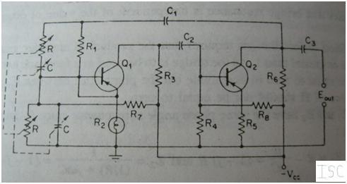
The micro power solar engine circuit is a compact design that utilizes low power components to achieve efficient operation. The core of the circuit comprises four transistors arranged to create a switching mechanism that drives the pager motor. The BC559C and BC559B transistors serve as the primary switching elements, controlling the flow of current based on the voltage levels detected at the base. The BC549C acts as a signal amplifier, ensuring that even minimal voltage changes can effectively trigger the motor.
The circuit's operation begins when the solar panel generates sufficient voltage to reach the firing point. This voltage is crucial for charging the capacitor, which temporarily stores energy. Once charged, the capacitor discharges through the motor, activating it for a brief moment. The feedback from the motor's operation helps maintain the conduction states of Q1 and Q2, allowing the circuit to stabilize at a low power draw while still providing enough current to drive the motor.
Resistor R1 plays a critical role in setting the base current for Q2, which in turn affects the overall performance of the circuit. By experimenting with different resistor values, it was determined that using a 560K or even a 680K resistor optimizes the performance without significantly impacting the circuit's responsiveness. The addition of R6 serves to protect the base of Q4, ensuring that the transistor operates within safe limits while maximizing the current available to the motor.
Further enhancements, such as the proposed substitution of Q4 with a ZTX618, could potentially lead to improved performance. This transistor is designed to handle higher voltages, which may increase the efficiency of the motor operation. However, the cost-benefit analysis of this change must consider the marginal gains in performance against the additional expense.
In summary, the micro power solar engine circuit represents a significant advancement in low-power robotics, showcasing the potential for sustainable energy solutions in small-scale applications. The careful selection of components and thoughtful design modifications contribute to a reliable and efficient circuit capable of driving small motors with minimal power input.A micro power solar engine has been a goal since my introduction to BEAM Robotics. I believe that if there wasn`t one before, I there is one now. What I`m presenting to you looks very similar to one of the circuits found in Steven Bolt`s web pages. As you will see, I made only minor changes to that design and not without help. My contributions h ave been to recognize the potential of the circuit, bread board and test it. The bottom line is that if you have a power source which will provide 2. 5Vdc at 10uA this circuit should drive a pager motor. It turns on the motor at 2. 3 to 2. 5Vdc and switches off at 1. 2 to 1. 5Vdc. Both Steve and I have built (bread boarded or haywired) the business end of the design and achieved similar results. This does not mean that it will work for everyone but it should. [I used a BC559C (Q1), a BC549C (Q2) a BC559B (Q3) and a BC337-25 (Q4), which happened to be in the bitbox.
SB] Enable power to the circuit. If the circuit works properly, the voltage will rise to a firing point, turn on the motor momentarily which discharges the capacitor to level where motor has little current passing through it but Q1 and Q2 are still conducting. At this point, . In practice, I removed R1, measured its value and replaced it with a standard resistor value 5 to 10% less.
560K was the value that both Steve and I used which shows just how repeatable this design is or how lucky we were. Note: It is realized that this presentation is very cryptic. If it were delayed until a complete circuit description and circuit layout were complete, it may not have been presented at all.
It is hard for many to realize the time and effort it takes to create the circuit cards, obtain the correct parts, make up the kits and write assembly / debug instructions. The dollar cost and other risks are not minimal. The first results from building a number of units. It was found that R1 could be replaced with a 680K resistor rather than using a pot. R6 was added to limit the current used to drive the base of Q4 which meant that more current became available for the motor.
390 Ohms is the smallest value that should be used for R6, it can be larger depending upon the motor and drive transistor (Q4) combination. There is one further proposed change that could improve the overall efficiency but it has not been tried, as far as I know.
Changing Q4 to a ZTX618 improves the voltage across the motor. It is manufactured by Zetex and available from Digi-Key, but the trouble and the price ($1. 08 US) may just not be worth it. 🔗 External reference
Related Circuits
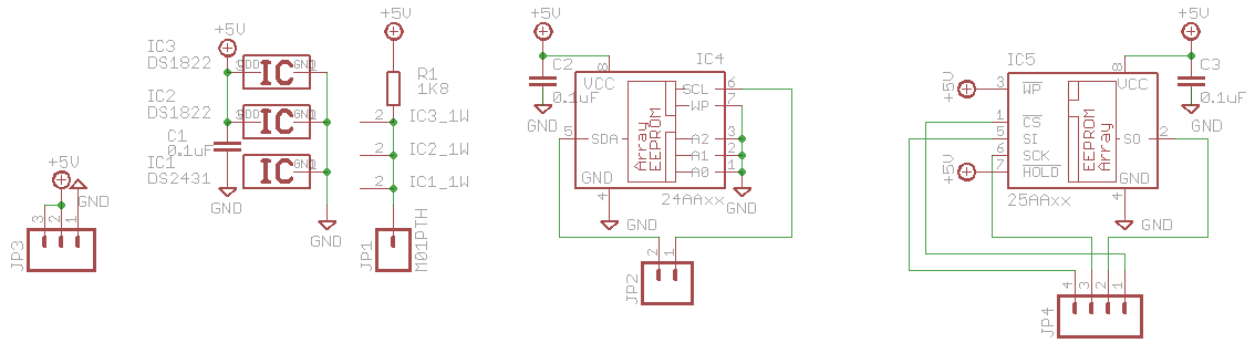
This is an outdated version; refer to the latest version on the documentation wiki. If you have one of Hack a Day's Bus Pirates, what should you do with it? Explore 1-Wire, I2C, and SPI EEPROMs using the 3EEPROM...
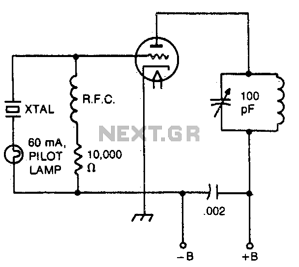
The pilot lamp limits current to prevent damage to the crystal. A very useful circuit. The circuit incorporates a pilot lamp designed to limit the current flowing to a crystal component, thereby safeguarding it from potential damage due to excessive...
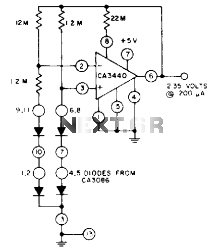
The circuit utilizes a CA3440 BiMOS operational amplifier and a CA3086 transistor array. The no-load current drawn from the 5-volt supply is 1.5 µA. The load current can reach up to 200 µA while still maintaining output voltage regulation...
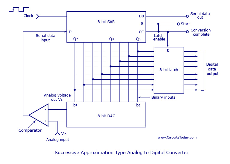
Analog to Digital Converters - Successive Approximation Type Analog to Digital Converter, working, circuit diagram. The Successive Approximation Register (SAR) Analog to Digital Converter (ADC) is a widely used type of ADC that converts an analog signal into a digital...
This bulletin outlines the applications, design features, equipment arrangement, and space planning for the type 230 controllers. These controllers are designed for the control and protection of induction motors or transformers in 2300-4160 volt systems. Each type 230 controller...
This article explains the construction and working of feedback oscillators, with a detailed description of the Wien bridge oscillator and phase shift oscillator, along with their circuit diagrams, basic components, and practical applications. Oscillators are electronic devices that produce...