
Type 230 Combination Controller
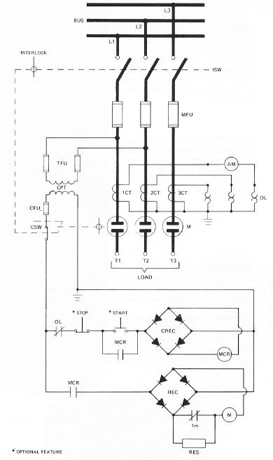
The type 230 controllers represent a robust solution for motor and transformer control in high-voltage applications. Each unit's design emphasizes safety, ease of maintenance, and operational efficiency. The vertical arrangement of components not only optimizes space but also enhances the accessibility of critical parts, facilitating routine inspections and repairs. The inclusion of thermal overload relays and current-limiting fuses provides a layered approach to fault protection, allowing for quick response times in the event of electrical anomalies. The ability to operate under substantial fault current conditions underscores the controller's reliability in demanding environments. Furthermore, the option for grouping multiple controllers with interconnecting buses allows for streamlined installations in larger systems, enhancing both functionality and safety. The thoughtful integration of manual isolating switches and mechanical interlocks further ensures that operators can maintain safe working conditions during maintenance activities. Overall, the type 230 controllers are engineered to meet the rigorous demands of modern industrial applications while prioritizing user safety and operational integrity.This bulletin outlines applications, design features, equipment arrangement, and space planning, for the type 230 controllers. These controllers are for the control and protection of induction motors or transformers on 2300-4160-volt systems.
Each type 230 controller is a coordinated combination of heavy-duty vacuum contactor, thermal overload rel ay, current transformers, and current-limiting fuses, with safety-interlocked isolating switch. The power elements are arranged vertically, for easy and safe installation and maintenance. Each controller requires only a 20" square of floor space. GENERAL The 230 controller provides full-voltage, non-reversing, magnetic starting and protection for induction motors. Or it may be used to switch and protect transformers. Alternate designs are available for synchronous motor control, reduced voltage starting, and other special applications.
SYSTEM CAPACITY These controllers may be used on power systems capable of producing fault currents up to 80, 000 ‘amps RMS asymmetrical. On a 3 ‘phase basis, that corresponds to 200, 000 ‘KVA at 2300 ‘volts and 350, 000 ‘KVA at 4160 ‘volts for symmetrical current calculations.
This assumes 1. 6 ratio between asymmetrical current and initial symmetrical current, for first-cycle fault interruption. LOCATION The 230 controller is ideal for indoor locations. In a minimum floor space, the design provides the safety and maintainability of one-high construction.
The 230 needs only 2. 78 square feet of floor space with working space required only in the front of the controller. LOADS The 230 ‘PM controller is made in two ratings: 180 ‘amp and 360 ‘amp. The 360 ‘amp rating may be used for up to 1500 ‘HP, 2300 ‘V, or 2500 ‘HP, 4160 ‘V. These general limits are for motors with 1. 15 service factor and up to a 6. 5 ratio of locked-rotor current to full-load current. GENERAL Each 230 Controller is a coordinated combination of a heavy ‘duty vacuum contactor, thermal overload relay, current transformers, and current limiting fuses, with safety-interlocked isolating switch. These major elements, with the accessory parts, are metal-enclosed, factory assembled, and interconnected.
The controller is front ‘connected with all parts readily accessible. The power elements are arranged vertically for easy and safe installation, operation, and maintenance. OPERATION A electromagnetically-operated vacuum contactor is the power switching element. The contactor, through a DC master relay, is controlled by the customer`s 115 ‘VAC pushbutton or other master element.
Optionally, start and/or stop control switches may be included in the controller. The contactor stays closed on momentary voltage dips but opens on prolonged loss of voltage. PROTECTION Three main-line fuses and two control transformer primary fuses provide high-speed fault protection with current-limiting effect. A 3-element thermal overload relay provides running overcurrent protection. The fuses are coordinated with the overload relays, so the contactor interrupts any overcurrents up to locked-rotor current and the fuses interrupt on fault currents.
Optionally, an instantaneous ground-fault current relay provides ground overcurrent protection on resistance or impedance grounded systems. SAFETY The isolating switch is manually operated to isolate the controller and the circuit from the power supply.
The isolating switch may be padlocked open or closed. The enclosure may be padlocked closed. A viewing window permits checking the isolating switch position, with the enclosure door closed. Mechanical interlocks prevent opening the door before opening the isolating switch or closing the isolating switch with the door open. An ammeter shows load current. GROUPING When grouped, each controller is in a separate enclosure, and the adjacent enclosures are bolted together.
Grouped controllers are equipped with self-contained, interconnecting main-bus. Controllers ma 🔗 External reference
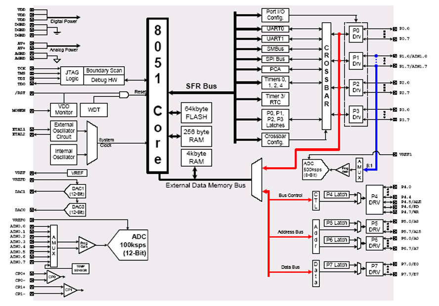
Related Circuits
The FM497 is an integrated electronic ignition controller designed for breakerless ignition systems that utilize Hall effect sensors. This device operates an external NPN Darlington transistor to manage the coil current, thereby delivering the necessary stored energy while maintaining...
The circuit operates by monitoring the water level in a tank. When the water level falls below a specified point (F), the RS flip-flop (F2) is activated, producing a high Q output that energizes a relay to start the...
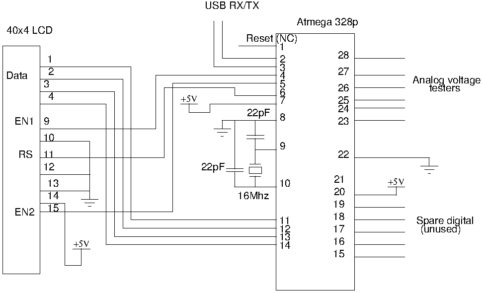
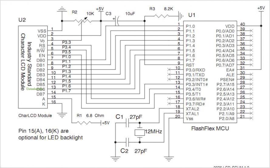
Drive a four-line LCD panel using an Arduino. The project initially aimed to control the LCD for displaying arbitrary information but evolved to include functionalities such as timekeeping, EEPROM read/write operations from the Atmel 328p, and voltage measurement. Multiple...
It is a miniature 10/100-MbBit Ethernet module that includes an integrated microcontroller. The price is less than $60. With its minimal dimensions of 1.38 in. x 2.16 in. (34.5 mm x 54 mm), the communications module can be used...
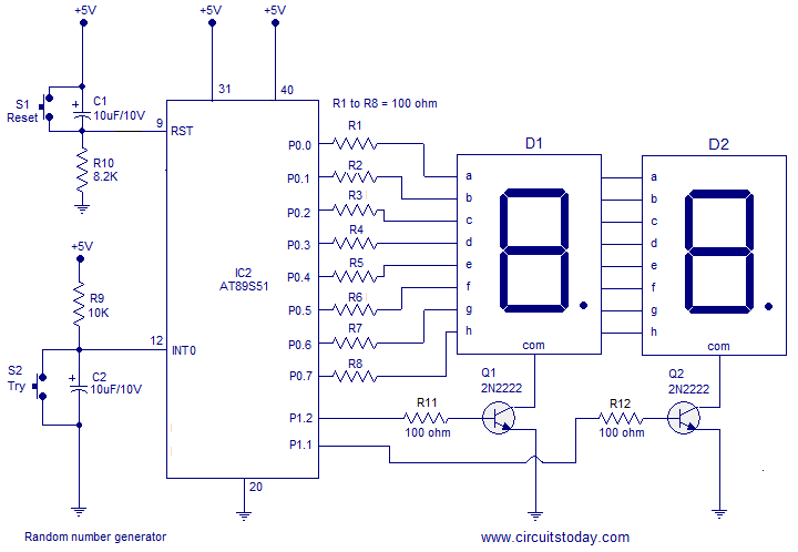
A simple random number generator utilizing the 8051 microcontroller. The AT89S51 is the controller employed in this setup. The circuit design for the random number generator based on the AT89S51 microcontroller involves several essential components and connections. The AT89S51 microcontroller,...
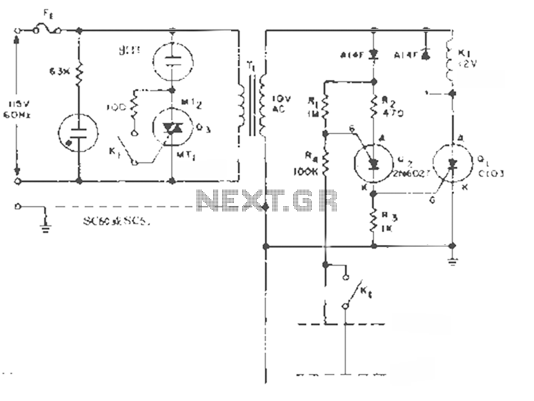
This circuit is designed to maintain the liquid level between two fixed points. By transforming the K1 contacts off the case, it can perform filling or extraction operations in two modes. The load can be either an AC motor...