
Midnight Security Light Circuit Schematic
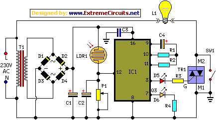
The energy-saving circuit described operates as a security measure by leveraging the natural light cycle to determine its activation time. The CD4060 IC serves as the core timing mechanism, utilizing its oscillator capabilities to manage the delay before activating the light source. The light-dependent resistor (LDR1) is critical for sensing ambient light levels; its characteristics allow the circuit to distinguish between day and night conditions.
During daylight, LDR1's low resistance keeps the reset pin of the IC high, effectively disabling the oscillator. As dusk falls, the resistance of LDR1 increases, causing the reset pin to go low and enabling the oscillator function. This results in a timed output that triggers the triac, which in turn controls the power to the light bulb.
The choice of components such as resistors R1 and R2, and capacitor C4, is crucial in determining the timing of the output signal. The design ensures that the light activates at a predetermined time, enhancing security during vulnerable hours. The use of capacitors C1 and C3 as power reserves is a thoughtful addition, allowing the circuit to maintain operation during minor power fluctuations.
The inclusion of a manual switch (S1) provides flexibility, allowing users to override the automatic function when necessary. Proper assembly practices, such as adequate spacing and lead sleeving, enhance the reliability and safety of the circuit. The enclosure should be designed to protect the internal components while allowing the LDR to receive sufficient light for accurate operation. Overall, this circuit represents a practical solution for enhancing home security during late-night hours, utilizing simple yet effective electronic components.Most thefts happen after midnight hours when people enter the second phase of sleep called paradoxical` sleep. Here is an energy-saving circuit that causes the thieves to abort the theft attempt by lighting up the possible sites of intrusion (such as kitchen or backyard of your house) at around 1:00 am.
It automatically resets in the morning. The circuit is fully automatic and uses a CMOS IC CD 4060 to get the desired time delay. Light-dependent resistor LDR1 controls reset pin 12 of IC1 for its automatic action. During day time, the low resistance of LDR1 makes pin 12 of IC1 high, ` so it doesn`t oscillate. After sunset, the high resistance of LDR1 makes pin 12 of IC1 low` and it starts oscillating, which is indicated by the fashing of LED2 connected to pin 7 of IC1. The values of oscillator components (resistors R1 and R2 and capacitor C4) are chosen such that output pin 3 of IC1 goes high` after seven hours, i.
e. , around 1 am. This high output drives triac 1 (BT136) through D5 and R3. Bulb L1 connected between the phase line and M2 terminal of triac 1 turns on when the gate of triac 1 gets the trigger voltage from pin 3 of IC1. It remains on` until pin 12 of IC1 becomes high again in the morning. Capacitors C1 and C3 act as power reserves, so IC1 keeps oscillating even if there is power interruption for a few seconds.
Capacitor C2 keeps trigger pin 12 of IC1 high during day time, so slight changes in light intensity don`t affect the circuit. Using preset P1 you can adjust the sensitivity of LDR1. Power supply to the circuit is derived from a step-down transformer T1 (230V AC primary to 0-9V, 300mA secondary), rectifed by a full-wave rectifer comprising diodes D1 through D4 and fltered by capacitor C1.
Assemble the circuit on a general-purpose PCB with adequate spacing between the components. Sleeve the exposed leads of the components. Using switch S1 you can turn on the lamp manually. Enclose the unit in a plastic case and mount at a location that allows adequate daylight. 🔗 External reference
Related Circuits

The touch control screen is a common feature in modern electronic products, typically incorporating a colored liquid crystal display (LCD) with a touch-sensitive interface. This technology is user-friendly and effectively replaces traditional fixed keypads. This document introduces the driving...
The TA8210AH integrated circuit (IC) is designed for use as an audio power amplifier in car audio systems. Typically, car audio setups include subwoofers and woofers, as the confined space of a vehicle does not require excessively high sound...

The servo motor is a type of traditional motor that serves as the execution component in automated devices. Its most significant characteristic is its controllability; when a control signal is applied, the servo motor rotates, with its speed being...
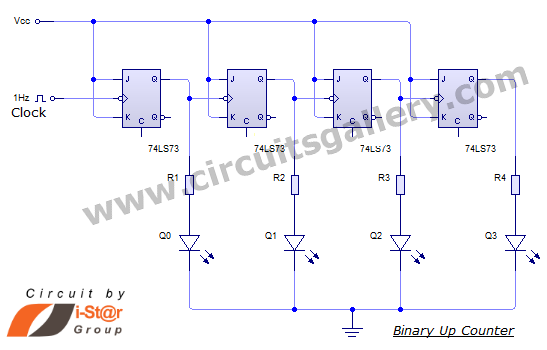
This document discusses an Asynchronous 4-Bit Binary Up Counter, a circuit constructed from several J-K flip-flops connected in a cascade configuration to produce a four-bit counting sequence. An up counter is a digital counting circuit that increments its count...
The digital counter circuit described utilizes an infrared signal to detect moving targets, making it suitable for counting small devices on a production line as they move along a conveyor belt. This circuit can also be employed for various...
A simple electronic circuit project is presented that can be constructed by any school student for display at a school science fair. The proposed circuit is a high-gain operational amplifier (op-amp) amplifier designed to detect the slightest RF disturbances...
Warning: include(partials/cookie-banner.php): Failed to open stream: Permission denied in /var/www/html/nextgr/view-circuit.php on line 713
Warning: include(): Failed opening 'partials/cookie-banner.php' for inclusion (include_path='.:/usr/share/php') in /var/www/html/nextgr/view-circuit.php on line 713