
Counter circuit diagram of the digital circuit
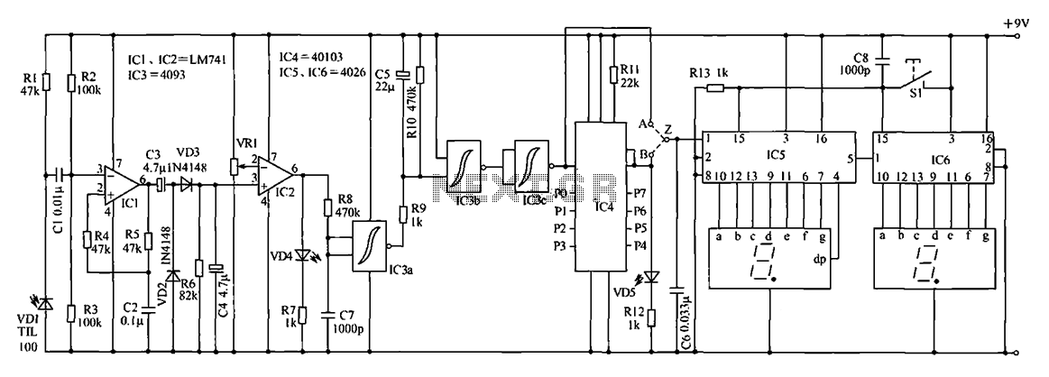
The digital counter circuit functions by employing an infrared light beam emitted by the transmitter, which is directed towards the target area. As an object, such as a vehicle or a package, interrupts the beam, the infrared receiver detects the change in signal. This interruption is interpreted as a counting event. The circuit can be configured to count objects in one direction or both, depending on the arrangement of the transmitter and receiver.
The infrared transmitter typically consists of an infrared LED that emits light in the infrared spectrum, which is invisible to the naked eye. The LED is driven by a simple transistor circuit that can be powered by a low voltage supply. The receiver is usually a photodiode or phototransistor that is sensitive to the infrared light. When the infrared beam is broken, the receiver generates a signal that can be processed by a microcontroller or a digital counter module.
In terms of implementation, the circuit can be enhanced with features such as adjustable sensitivity, allowing it to detect objects of varying sizes and reflectivity. Additionally, a debounce circuit may be included to prevent multiple counts from a single object passing through the beam. The output from the receiver can be connected to a display module, such as a seven-segment display, to provide a visual representation of the count.
Overall, this digital counter circuit is an efficient solution for counting applications across various industries, providing accurate and reliable results while maintaining a straightforward design that can be easily integrated into existing systems.Digital counter circuit as shown is composed of infrared signal for detection of moving target scan count small device, it is suitable for the production line, to move items on the conveyor belt for quick and accurate count. It can also be used for other purposes, such as passengers or the exit of the pit mouth was counting. The characteristics of the circuit is a simple structure, easy, economical and practical. But the most prominent advantage is that it can often different shading anything can intuitively and accurately counted.
For example, from one side to see the cars have both front and rear wheels to be scanned, which requires the scanning signal is divided by two and then count, in order to obtain correct results. The device consists of an infrared transmitter and receiver of two parts.Infrared transmitter circuit:
Related Circuits
Motor Bike Headlight Controller Circuit. This circuit automatically turns a motorcycle's headlight on and off, independently of both the light and ignition switches, provided the battery is fully charged. The first stage... The motorcycle headlight controller circuit is designed to...
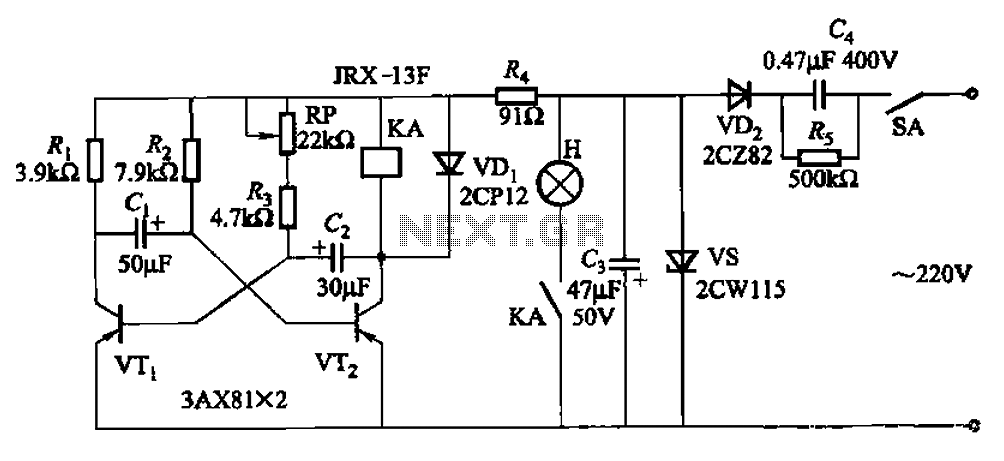
The circuit features a self-excited multivibrator composed of transistors VTi and VTZ. It includes an adjustment potentiometer RP and two RC networks that influence the transistors' parameters, specifically the timing for light activation and deactivation. The described multivibrator circuit utilizes...
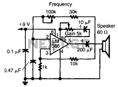
An LM386 audio power IC is configured as a feedback oscillator. It can operate with a supply voltage ranging from 6 to 12 V. The circuit is capable of driving a loudspeaker. The LM386 is a low-voltage audio power amplifier...
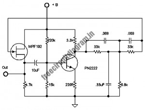
The following circuit illustrates a stable 60 Hz frequency signal generator circuit diagram. Features include a 0.068 µF capacitor incorporated within a feedback loop, allowing for DC-to-AC conversion. This circuit is designed to generate a stable 60 Hz sine wave...
The circuit incorporates components Q, C, and ZD, which are responsible for the bias and buffer stages. Its primary objective is to ensure stable MOSFET gate operation and provide an offset voltage through a voltage buffer amplifier stage with...
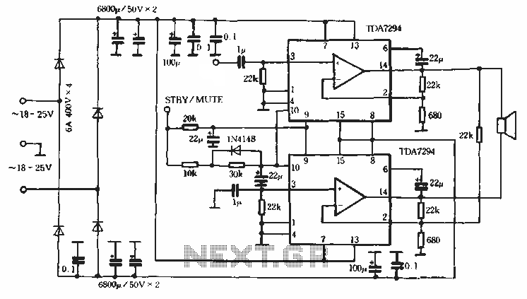
Europe's leading SGS-THOMSON STMicroelectronics recently introduced a new power integrated amplifier, the TDA7294, to the Chinese mainland market. This amplifier, characterized by a cold and hard tone, is particularly suited for Hi-Fi applications such as home theaters and active...