
Mini efficient coil launcher from disposable camera flashs
The project involves creating a coil gun, which utilizes electromagnetic principles to accelerate a ferromagnetic projectile. The basic operation relies on the principles of inductive coupling and electromagnetic induction. When the coil is energized, a magnetic field is generated, pulling the projectile into the coil. The challenge lies in timing the power pulse so that it is cut off just as the projectile reaches the center of the coil, preventing it from being pulled back once the magnetic field collapses.
To achieve optimal performance, the coil's design is crucial. The choice of wire gauge, number of turns, and layering affects the inductance and resistance of the coil. A higher number of turns increases the inductance, which can limit the peak current, while a lower resistance allows for a quicker discharge of the stored energy in the capacitors. The use of a glass tube as a barrel is advantageous due to its non-magnetic properties which minimize eddy current losses.
The SCR serves as the primary switching device, allowing for rapid control of the power pulse. Its selection is based on the required current and voltage ratings, ensuring that it can handle the peak currents without failure. The addition of a reverse diode protects the SCR from back EMF generated when the coil is de-energized, which could otherwise damage the switching component.
In summary, this project represents a practical application of electromagnetic principles in a fun and educational context. It combines elements of circuit design, component selection, and timing analysis, making it an excellent exploration of physics and engineering concepts.This is a fun and non-dangeros project for those people who like to throw projectiles magnetically. It simply works by placing a ferromagnetic projectile at one end of a coil and pulsing some power in it. The trick is to switch off power when the projectile is at the middle of the coil, there are some ways to do it but it isn`t important now.
The second trick is to use a coil as close as possible to projectile to waximize coupling and the third to avoid saturation, that means keeping the current not to high. I`ve been messing with coil launchers for a year. The first model was a straw with some wire wrapped on it and an electrolityc capacitor (200V) pulsed in it.
Lots of sparks and metal flying but was able to shoot a nail accross my room. I started esperimentation wrapping wire on glass and using more litycs charged by mains power, very bulky and disappointing (100J of energy where only able to blast through 2 sheets). After holydays I started more mature experimentation employing SCRs (solid state switching) photoflash electrolytics and optical sensors, and built a bi-coil launcher (2 stages), complicated but poweful ( blasted through a can) but the timing is critical, so transient simulations were a must (and a L-C-R meter).
The next launcher will be mosfet-switched with 3 coils and optical sensors, but i don`t have the funds/parts yet to build such an expensive launcher, but already designed plans and models. For now i decided to build a small funny coil launcher using one scr and coil on glass. Using my LCR meter and multisim simulator i designed it for max efficiency. For first you need some disposable camera flashes, so try to search at your local photo shop. You need 4 of more of them. Desolder the caps and collect them. They have ratings of 330V 120-160uF and can survive pulses up to 300A (each), or even dead shorts (but don`t do it because it is quite a bang).
Paralleling them reduces the ESR (internal resistance) and ESL and highers peak current capability. I used 4 of them and my coil launcher has a pulse current of 400A (about 100A for cap). The more caps, the more energy but more longer pulse, so the additional energy may slow down the projectile instead of fastening it so I would advice to keep them only 4. I trusted the simulations and have almost broken a window with this thing ;-) fortunately the curtains slowed it down.
Concerning the charging circuit, use the largest you got, and try to use more batteries than originally if you want a fast charge. I used a max kodak disposable flash and it works fire with 4 1. 5V batteries (originally it was designed to use one) and doesn`t burn out. The caps where soldered on a small breadboard with parallel tracks made with lots of solder (otherwise the solder will blow).
The coil was made with 200 turns distributed on 10 layers (rembember to insulate eachover) of insulated magnet wire with 1mm diameter on a glass pipe with 6 mm external diameter and 3 mm internal diameter. Also plastic works good as barrel but must be hard, metals must be NON-Ferromagnetic and must have a cut along the barrel lenght (to limit eddy currents).
The resistance is 350 milliohm and inductance is 165 uH (according to my LCR meter) giving a pulse lenght of 1 ms (Multisim simulation) and peak current of 400A, limited by inductance. Using more caps would increase pulse current because the resistance is low and the current is Inductance-limited, so i advice to use only 4 caps (maximum 5).
Concerning the switching i used 2N6509 SCRs (Onsemi) (25A 800V) which have a pulse rating of 300A x 6 ms (450 x 1ms). They are very good cheap and small and requires small signal to drive. A reverse diode was added to the caps because the simulations showed a peak reverse 🔗 External reference
Related Circuits

This circuit is designed as a pocket-sized, high-performance audio oscillator. It can operate using a battery-powered version, which is feasible at a very low cost by utilizing a single quad op-amp to provide the entire active circuitry. The design...

This project is designed to provide security for personal belongings left on a beach towel while swimming or engaging in other activities. The project involves creating a portable electronic alarm system that can be easily set up on a...
Every inexpensive energy-saving lamp contains a self-resonant voltage inverter designed for low-power operation, typically up to a few watts. It raises the question of why not scale up this concept and replace the resonance circuit used to generate the...
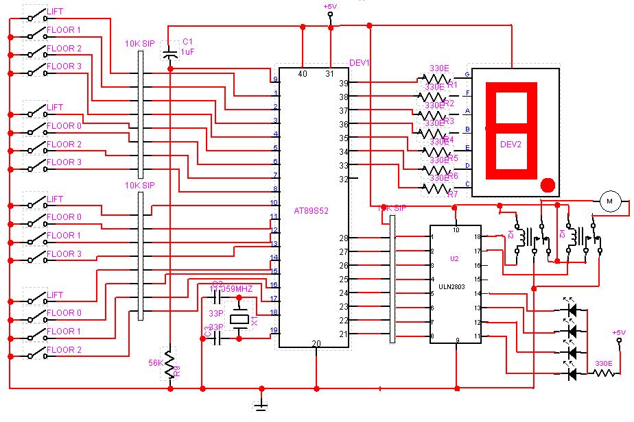
A circuit design has been conceptualized, and an Assembly code program has been drafted for a three-level mini system. The described circuit design focuses on a three-level mini system, which can be interpreted as a hierarchical structure where each level...

The AVR Microcontroller and high-performance 2.4GHz RF transceiver ATMEGA128RFA1 is an IEEE 802.15.4 compliant single-chip device. It integrates the industry-leading AVR Microcontroller with a top-tier 2.4GHz RF transceiver, offering the highest RF performance for single-chip devices, featuring a link...
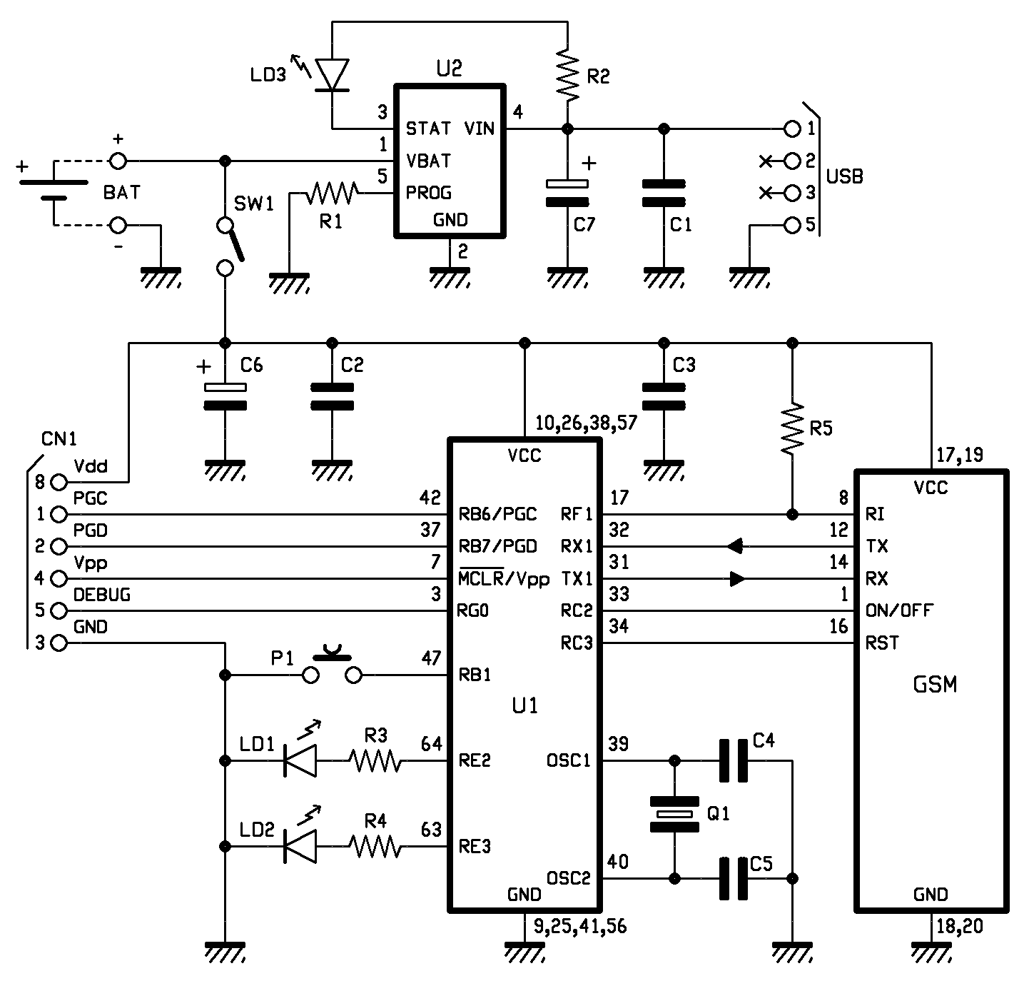
A localizer that does not utilize GPS technology has been developed using the cost-effective SimCom SIM900 module. In previous discussions, the GSM section was presented, and now the complete localization system is introduced. This system allows for object localization...
Warning: include(partials/cookie-banner.php): Failed to open stream: Permission denied in /var/www/html/nextgr/view-circuit.php on line 713
Warning: include(): Failed opening 'partials/cookie-banner.php' for inclusion (include_path='.:/usr/share/php') in /var/www/html/nextgr/view-circuit.php on line 713