
3 level mini elevator semi finished needs debugging
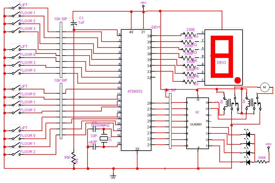
The described circuit design focuses on a three-level mini system, which can be interpreted as a hierarchical structure where each level serves a specific function or purpose. This type of design is often utilized in applications such as control systems, data processing units, or educational projects aimed at demonstrating fundamental electronic principles.
The first level of the system typically involves input processing, where sensors or user interfaces collect data. This level may include components such as resistors, capacitors, and operational amplifiers to condition the input signals for further processing. The Assembly code written for this level is crucial for interpreting the raw data, managing input signals, and ensuring that they are formatted correctly for the next stage.
The second level is often focused on data manipulation and decision-making processes. Here, microcontrollers or microprocessors play a vital role, executing the Assembly code to perform calculations, logic operations, and control functions. This level may also involve memory elements to store temporary data and results from the input stage, which can be utilized in real-time applications.
The third level typically encompasses output generation, where the processed data is translated into actionable outputs. This could involve driving motors, lighting LEDs, or sending data to displays. The Assembly code in this stage is responsible for managing the output devices, ensuring timely and accurate responses based on the processed inputs and decisions made in the previous level.
Overall, the integration of these three levels within the circuit design allows for a modular and efficient system that can be adapted for various applications. The careful consideration of each level's functionality, along with the corresponding Assembly code, is essential for achieving optimal performance and reliability in the final product.Hi to all So I have come to a point where I was able to think about a certain circuit design and write the Assembly code program for my 3 level mini .. 🔗 External reference
Related Circuits
Generating and manipulating sine wave functions is a common challenge faced by circuit designers. Sine wave circuits present significant design difficulties because they function as continuously controlled linear oscillators. Such circuitry is essential in various fields, including audio testing,...
This circuit utilizes two quad op-amps to create an eight LED audio level meter. The op-amp employed in this circuit is the LM324, a widely used integrated circuit that is readily available from numerous electronic component suppliers. The 1K...
The four main input channels are identical and feature independently adjustable input sensitivity, tone, and sound panning. The fifth input is a linear channel. Despite its inexpensive and basic design, the Mini Audio Mixer "Impulse MM-04" performs satisfactorily. The Mini...
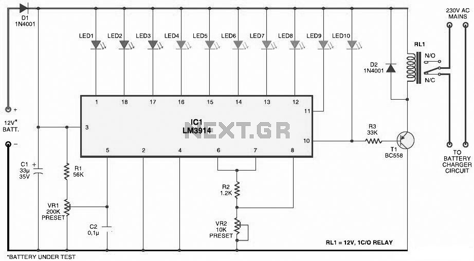
This document presents a circuit diagram for a simple and easy-to-construct battery level indicator. Typically, in mobile phones, battery levels are shown in either dot or bar format, allowing users to easily recognize the battery status. The battery level indicator...
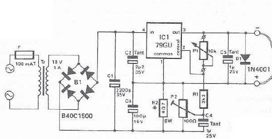
An integrated voltage regulator connected in reverse to a mini drill allows for speed adjustment within specific limits, maintaining a constant speed regardless of load. The electronic speed control is achieved through a voltage regulator, which can power motors...
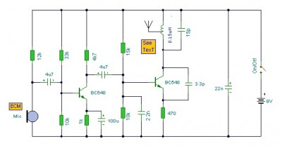
This is a mini FM transmitter circuit that utilizes two transistors. The audio sensitivity is notably high when paired with an ECM type microphone. The transmitter operates using a Hartley oscillator configuration. Typically, the capacitor in the tank circuit...