
MINI ROULETTE
The described circuit operates as a compact and engaging roulette simulation, ideal for educational purposes or entertainment. The 4017 decade counter is a versatile component that counts pulses from the clock signal generated by the 555 timer. This configuration allows for the sequential illumination of each LED, creating a visually appealing effect that mimics the spinning of a roulette wheel.
The 555 timer, functioning in astable mode, continuously generates a square wave signal. The frequency of this signal is determined by the values of the timing capacitor (C2) and resistor (R3). The design choice of C2 directly impacts the speed of the LED cycling; larger capacitance will result in a slower cycle, while smaller capacitance will increase the speed. Resistor R3 plays a crucial role in ensuring that the circuit remains stable during operation, particularly when the SPIN button is activated and the LEDs are in motion.
The common limiting resistor R4 is essential for protecting the LEDs from excessive current, ensuring their longevity and consistent brightness. The arrangement of the LEDs in alternating colors not only enhances the aesthetic appeal but also helps in distinguishing the active LED during gameplay.
The inclusion of the piezo disk transducer (X1) adds an auditory element to the circuit, further enriching the user experience. This component converts the electrical oscillations from the 555 timer into sound waves, providing feedback that complements the visual display.
Overall, this mini battery-powered roulette circuit is a well-rounded project that combines principles of digital electronics, timing circuits, and sound generation, making it an excellent demonstration of basic electronic concepts.A circuit diagram for a mini battery-powered version of roulette is shown, This circuit uses a 4017 decade counter (IC2) driving 10 LEDs. Because only one LED is ever illuminated at any one time, a common limiting resistor R4 is used. They can also be placed in alternating red/green order for added effect. The counter IC2 is clocked by IC1, a clas sic 555 timer connected as an astable. When the SPIN button is pressed and then released, full speed is achieved, and then the display gradually slows down until it stops on a single number. Capacitor C2 governs the oscillator speed, and resistor R3 prevents instability when the LED rotation stops.
The piezo disk transducer, X1, is placed on the output of the oscillator to provide a sound effect. 🔗 External reference
Related Circuits
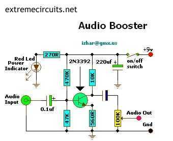
This small amplifier circuit is ideal for boosting small audio units. The small amplifier circuit is designed to enhance the audio signals from low-output devices, such as microphones or portable music players. It typically employs a transistor or an operational...
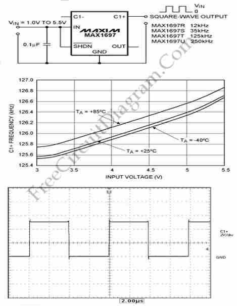
This circuit generates a square wave, which is useful as a clock signal or AC drive for the excitation of sensors. This article presents a square wave. The square wave generator circuit is designed to produce a periodic waveform that...
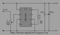
The TDA7052 is a mono output amplifier housed in an 8-pin Dual In-line Package (DIP). This device is specifically designed for use in battery-operated portable audio applications. Key features of the TDA7052 include the absence of external components, elimination...

Q1 & Q2 provide linear frequency operation of IC1 following P1 resistance variation. Q3 was added in order to obtain a louder click, similar to clockwork metronomes. A 12V micro battery was used to obtain a higher output power...
This is a selection of small self-contained alarm circuits. They have a very low standby current; and are suitable for battery operation. The described alarm circuits are compact and designed for low power consumption, making them ideal for battery-powered applications....

When switches SW1, SW2, or SW3 are open, the input sensitivity is optimized for high-output devices such as CD players, tuners, tape recorders, iPods, miniDisc players, and computer audio outputs. The 750 Ohm value for resistors R3, R13, and...