
Square Wave Oscillator with Minimum Components Count
The square wave generator circuit is designed to produce a periodic waveform that alternates between a high and a low state, making it suitable for various applications in electronics, including clock signals for digital circuits and AC drive signals for sensor excitation. The key components typically involved in this type of circuit include resistors, capacitors, and active devices such as operational amplifiers or transistors.
In a basic square wave generator, a resistor-capacitor (RC) network is often used to determine the frequency of oscillation. The charging and discharging of the capacitor through the resistor creates a time delay that defines the duration of the high and low states of the output waveform. The output can be taken from a comparator or a transistor that switches states based on the voltage across the capacitor.
For instance, in a simple astable multivibrator configuration using two NPN transistors, the circuit can be designed to toggle between the high and low states based on the feedback from the output to the base of the transistors. This arrangement allows for the generation of a continuous square wave without requiring any external triggering.
The frequency of the output square wave can be adjusted by changing the values of the resistors and capacitors in the circuit. Additionally, the duty cycle, which determines the proportion of time the signal is high versus low, can also be modified by manipulating these component values.
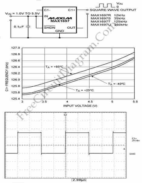
In practical applications, square wave signals can drive various loads, including relays, LEDs, and other electronic components. The waveform's characteristics, such as rise and fall times, can be influenced by the circuit design and component selection, ensuring compatibility with the intended application. Overall, the square wave generator circuit is a fundamental building block in electronic design, providing essential timing and control signals across a wide range of devices.This circuit generates a square-wave which is useful as a clock signal or AC drive for the excitation of sensors. this article presents a square-wave. 🔗 External reference
Related Circuits
The ML7005 is a multi-functional DTMF transceiver LSI that incorporates a DTMF signal generator, a DTMF signal receiver, a call progress tone generator, a call progress tone detector, and a FAX (FX) signal detector. Each functional block can be...
This simple alarm circuit can effectively alert users to the presence of an intruder, providing notification before they even reach the doorstep. The circuit is designed to be straightforward and efficient, utilizing basic electronic components to create an effective security...
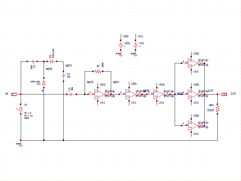
This schematic example demonstrates a sinusoidal voltage input at a frequency of 10 kHz, which is converted to a square wave using an inverter-based circuit. The VDD and VSS rails are connected to +1V and -1V, respectively. The control...
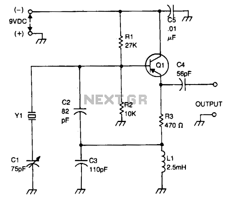
Bias for the PNP bipolar transistor is supplied by a resistor voltage divider network consisting of resistors R1 and R2. The collector of the oscillator transistor is maintained at AC ground through a capacitor C5, which is positioned near...
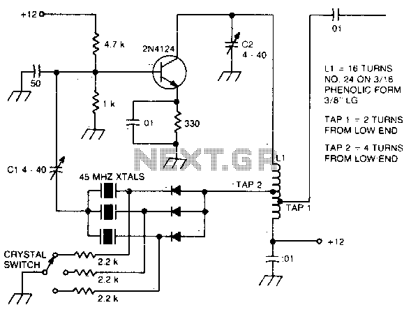
The large inductive phase shift of LI is compensated for by Cl. Overtone crystals have very narrow bandwidth; therefore, the trimmer has a smaller effect than for fundamental-mode operation. The statement discusses the compensation of inductive phase shifts in a...
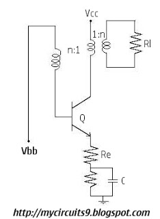
Initially, there is a voltage Vc on capacitor C1 that is greater than Vbb - Vg, where Vg is the cutoff base-emitter voltage and g represents Gamma. Consequently, the transistor is in the off state, and capacitor C1 discharges...