
MK414 SW Receiver
The MK414 is a versatile integrated circuit designed for use in low-frequency radio receivers. With a maximum working frequency of around 4 MHz, it is capable of handling shortwave signals up to 6 or 7 MHz, making it suitable for various amateur radio applications. The use of a 10k resistor to control the operating voltage is essential, as it ensures that the IC operates within its specified parameters, thereby enhancing performance and reliability.
The tuned circuit, which is a critical component of the receiver, consists of a variable capacitor and a fixed air-spaced coil. The coil, constructed with 10 to 20 turns of wire, is wound around a tube with a diameter of approximately 1.5 inches. This design allows for a compact form factor while maintaining effective inductance. The overall length of the coil is about 3 inches, which contributes to the tuning characteristics of the circuit.
The variable capacitor, adjustable from 0 to 300 pF, provides flexibility in tuning the receiver to different frequencies. This adjustability allows users to experiment with different configurations to optimize performance based on specific reception conditions.
To facilitate effective signal reception, an external antenna is required. A wire antenna measuring approximately 7 meters in length has been identified as effective for this application. The antenna can be connected either at one end of the coil or through a series capacitor, with values ranging from 10 pF to 100 pF, which can further enhance tuning and reception capabilities.
Overall, this configuration of the MK414 receiver circuit, with its tuned circuit and antenna setup, provides a robust platform for receiving shortwave broadcasts, allowing for experimentation and optimization in various radio applications.The original data sheet for the MK414 states a maximum working frequency is around 4 MHz. SW transmissions are so powerful that this receiver will work well with signals up to about 6 or 7 MHz. The 10k resistor controls the operating voltage for the IC which is critical for good performance. The tuned circuit consists of a variable capacitor and f
ixed air spaced coil. For the coil, I wound between 10 and 20 turns of wire on an empty tube of around 1. 5 inches diameter. The turns were spaced so that the overall length was around 3 inches. The variable capacitor tuned 0 - 300 pF but there is plenty of scope for experiment here. One final point, you will need an external antenna to receive broadcasts. I have an outside wire that is about 7 meters long and this was quite effective. The antenna can be connected at either end of the coil or via a series capacitor value between 10pF and 100pF.
🔗 External referenceRelated Circuits

The TEA5551T monolithic integrated radio circuit can be utilized to design an AM radio receiver, intended for use as a portable radio receiver with headphones. The TEA5551T radio receiver circuit encompasses all necessary components for a complete AM receiver,...
This application note explains the operation of the data slicers found in the Maxim line of UHF receivers such as the MAX1470, MAX1473, and MAX1471, as well as transceivers like the MAX7030 and MAX7032. The data slicers in the Maxim...
Briefly it's an Infrared receiver which communicated with your pc to command many windows application, so once you have built the interface, programmed the pic16f84 with the code and connected everything to your serial com2 you'll be able to...
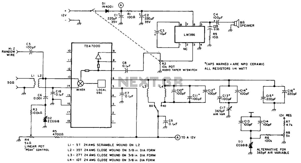
This direct-conversion receiver utilizes a TDA7000 integrated circuit (IC) and incorporates an LM386 audio amplifier. The TDA7000 serves as the mixer and local oscillator (L.O.) section. The frequency control can be achieved using either an air variable capacitor or...
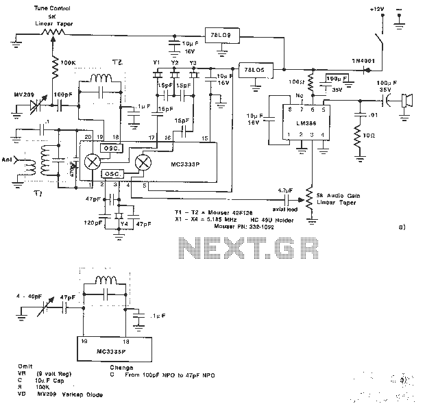
The MC3335P is a low-power narrowband FM receiver that can be used to design a very simple 80 m SSB receiver. The MC3335 also features a comparator circuit for FSK detection. The circuit is straightforward and requires few external...
This project is a PLL synthesized FM radio which can decode DTMF. The receiving frequency can be set by the PLL circuit from 80-140MHz. The receiver is VERY stable, high sensitivity and easy to build and tune. The FM...