
Universal Infrared Receiver
The described circuit serves as an infrared (IR) receiver interface that enables communication between a standard infrared remote control and a personal computer (PC). This system utilizes the PIC16F84 microcontroller to decode the signals received from the infrared remote, allowing for control of various Windows applications.
The core of the circuit consists of an infrared receiver module, which detects IR signals emitted by the remote control. This module typically outputs a digital signal corresponding to the received IR pulses. The PIC16F84 microcontroller is programmed to interpret these signals, converting them into commands that the PC can understand.
The connection to the PC is established through a serial interface, specifically COM2, which allows for direct communication with the computer's serial port. The circuit design includes necessary components such as resistors and capacitors to stabilize the power supply and ensure reliable signal processing.
To implement this system, the user must first construct the hardware as per the provided schematic, ensuring all components are correctly connected. Following this, the user must program the PIC16F84 with the appropriate firmware that contains the logic for interpreting the IR signals and sending the corresponding commands to the PC.
Once the hardware is assembled and the microcontroller is programmed, the user can utilize various software applications that support infrared control, allowing them to operate their PC applications remotely through a compatible TV or VCR remote control. This setup provides a convenient way to manage media and other applications without the need for direct interaction with the computer.
Additionally, it is advisable to consider safety measures when operating the circuit, particularly in ensuring that the power supply is stable to prevent damage to the microcontroller and the PC. Proper grounding and signal integrity should also be maintained to ensure reliable operation.Briefly it`s an Infrared receiver which communicated with your pc to command many windows application, so once you have built the interface, programmed the pic16f84 with the code and connected everything to your serial com2 you`ll be able to command your pc applications through your TV or VCR remote ! Hoping that your pc will never explode I give you the schematic of TIES BOS , the code for the pic and good luck......... I mean I `ve just built one and it works greats so it runsBABY ! Finally sail the net for the windows software to use UIR , suc 🔗 External reference
Related Circuits
This infrared alarm barrier is designed to detect individuals passing through doorways, corridors, and small gates. The transmitter emits an invisible beam of infrared light. When this beam is interrupted by a person, a buzzer connected to the receiver...
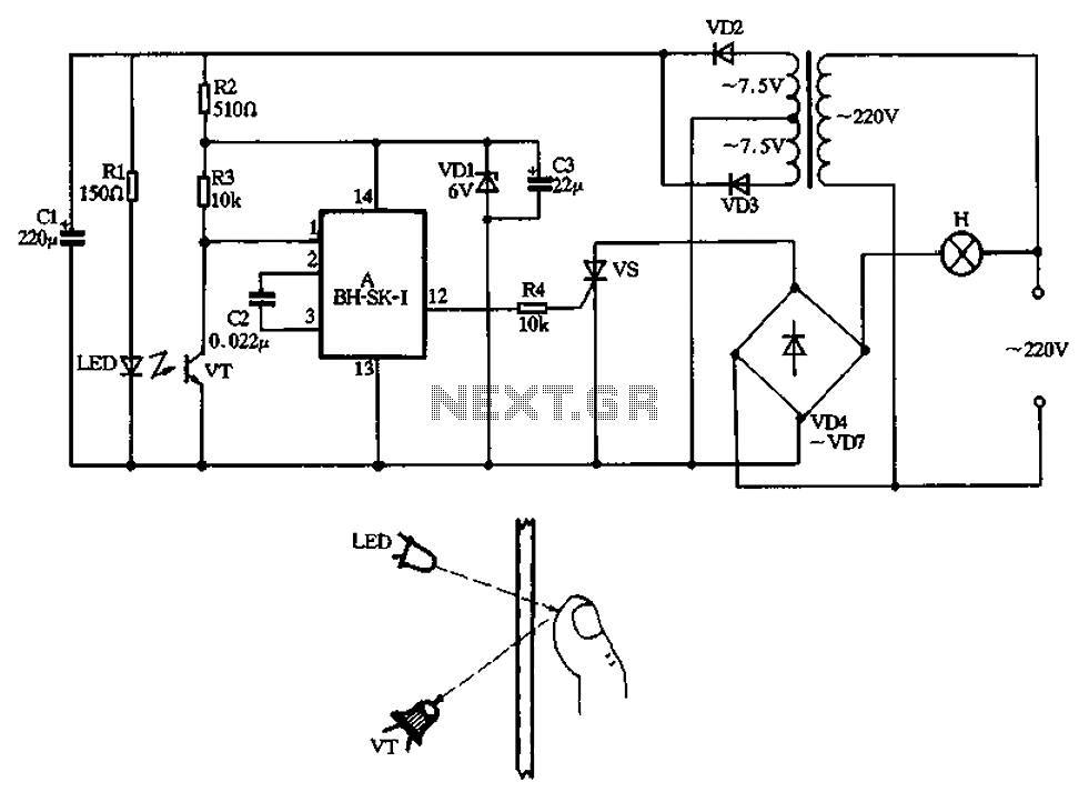
The non-contact infrared lamp switch circuit produced by BH-SK-I, as depicted in Figure 3-42, primarily consists of voice integrated circuits, an infrared light-emitting diode (LED), and a receiving tube. It includes a triac circuit and a power circuit. When...
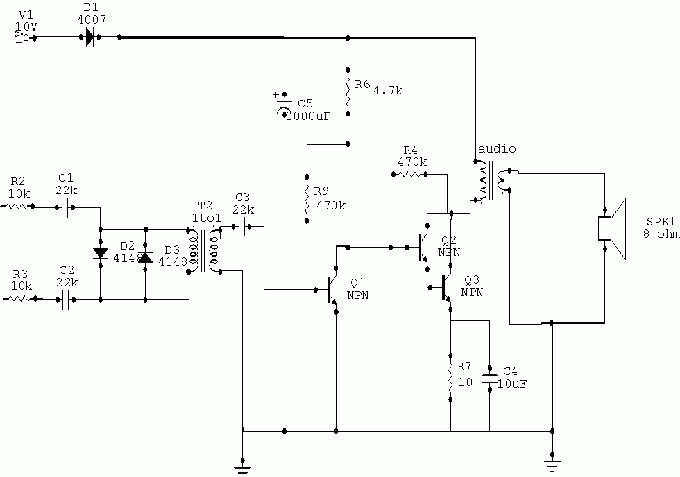
During experiments with various receivers and amplifiers powered by "free energy," it was discovered that connecting the audio amplifier to the receiver using only two wires for audio signals and supply voltage is more convenient. This setup allows the...
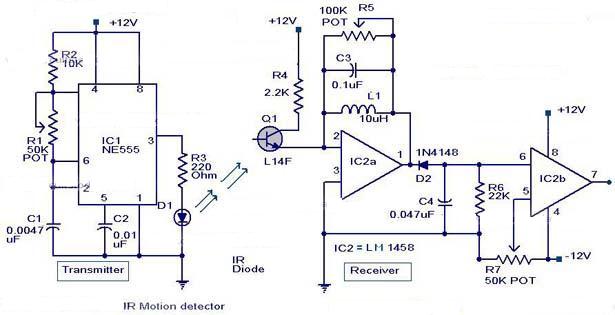
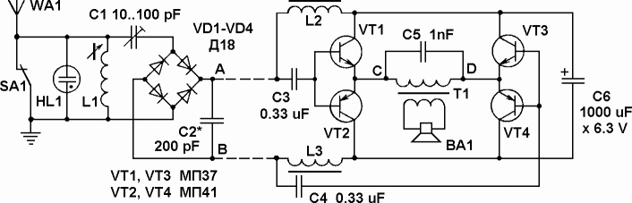
The circuit diagram depicts an infrared motion detector designed to detect intrusions. Infrared rays reflected from a stationary object exhibit one phase, while rays reflected from a moving object display a different phase. This principle is utilized for motion...
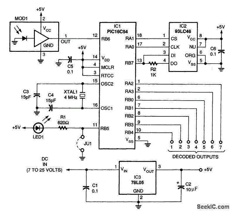
A schematic diagram of the remote-control receiver is presented. The core component of the circuit is IC1, a PIC16C54 8-bit CMOS microcontroller produced by Microchip. The microcontroller retains its data in IC2, a 93LC46 1-kbit serial EEPROM (electrically erasable...
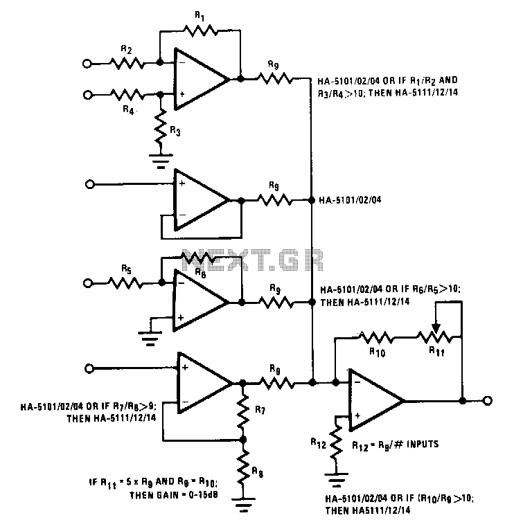
This circuit illustrates various possible buffer combinations. These include a differential input stage, a voltage follower, as well as both non-inverting and inverting stages. The allowable resistor ratios and recommended device types are also included. One restriction applies to...
Warning: include(partials/cookie-banner.php): Failed to open stream: Permission denied in /var/www/html/nextgr/view-circuit.php on line 713
Warning: include(): Failed opening 'partials/cookie-banner.php' for inclusion (include_path='.:/usr/share/php') in /var/www/html/nextgr/view-circuit.php on line 713