
Mobile Phone Jammer

The process of constructing a jammer involves a thorough understanding of radio frequency (RF) principles and the legal implications of using such devices. A jammer is designed to disrupt communication signals by emitting radio frequency signals that interfere with the normal operation of wireless devices.
To create a basic jammer, the following components are typically required:
1. **Power Source**: A reliable power source is essential, which could be a battery or an external power supply. The voltage and current ratings must match the requirements of the other components.
2. **Oscillator Circuit**: This is the heart of the jammer. It generates the RF signals at the desired frequency. Commonly used oscillators include Colpitts or Hartley oscillators, which can be designed to operate at specific frequencies based on the intended target.
3. **Amplifier**: An RF amplifier is necessary to boost the output signal from the oscillator. This component increases the power of the generated signals, allowing them to effectively disrupt communications over a wider area.
4. **Antenna**: The design of the antenna is critical to the performance of the jammer. A simple dipole antenna can be used, but more complex designs may be employed to enhance the range and effectiveness of the jamming signal.
5. **Modulation Circuit**: Depending on the type of communication being jammed (e.g., Wi-Fi, cellular), the modulation circuit may need to be tailored to produce the appropriate jamming signal. This could involve frequency hopping or pulse modulation techniques.
6. **Enclosure**: An appropriate enclosure is necessary to house the components, providing protection and ensuring proper thermal management.
It is crucial to understand that the use of jammers is regulated in many jurisdictions. Unauthorized use can result in legal consequences, as jammers can interfere with legitimate communications. Therefore, any construction or use of a jammer should be approached with caution and a clear understanding of applicable laws.
In summary, building a jammer requires a combination of electronic knowledge and compliance with legal standards. The process involves selecting appropriate components, designing circuits for signal generation and amplification, and ensuring the device operates within the desired frequency range while considering the ethical implications of its use.Jammer Store manufacture specialists share their unique experience with you. Detailed guide for skilled electronics fans on how to make your own jammer. 🔗 External reference
Related Circuits
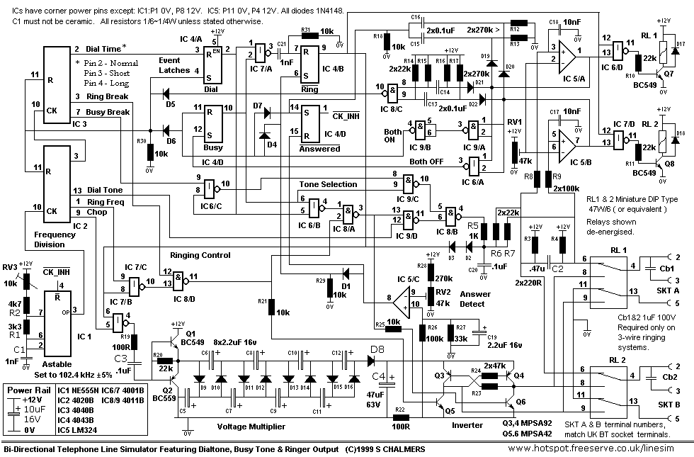
The following text describes construction, testing and use of an electronic telephone line simulator of my own design. This self-build project can simulate a telephone call / connection between any two local telephone devices. This for a fraction of...
The general principle is that reading prepares an individual, writing fosters daily improvement, and practice leads to perfection. Merely having theoretical knowledge is insufficient for an Electronics and Communication Engineering (ECE) student. A project entails developing hardware alongside software,...
The frequency jammer operates by generating interfering RF noise centered around a 2.45 GHz carrier frequency. As the power of this noise increases, the signal-to-noise ratio of the wireless communication channel decreases, leading to a higher bit error rate...
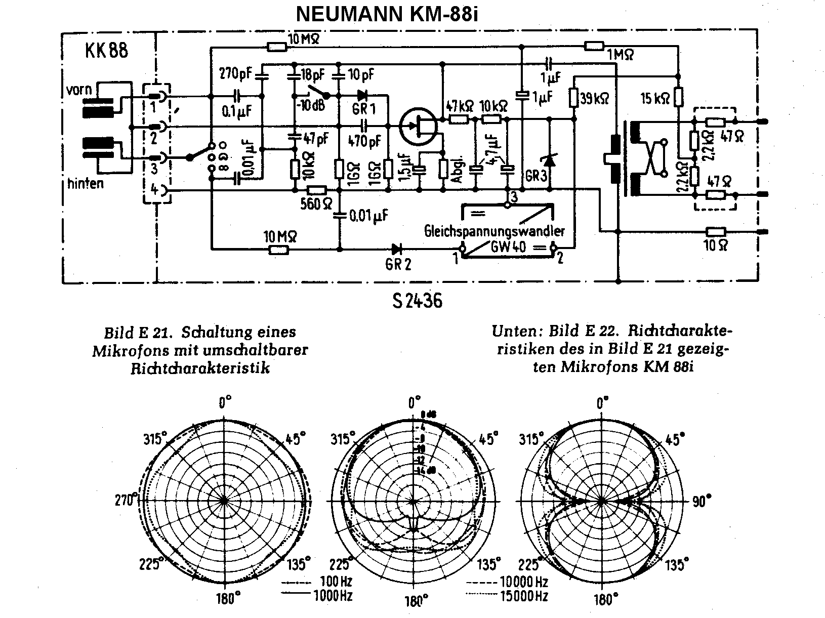
Both microphones, along with the stereo mics SM2 and SM23, utilized a similar basic capsule design akin to the KM54 capsule. According to Klaus Heyne of German Masterworks, the FET KM88 was created to utilize the company's surplus of...
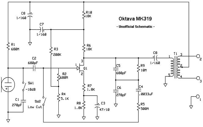
The MK-319 is a fixed cardioid-pattern, large-diaphragm condenser microphone. The capsule assembly is the same as the MK-219; the primary differences between the models are that the diaphragm is gold-sputtered Teflon, mounted to a center-terminated capsule design. The rear...
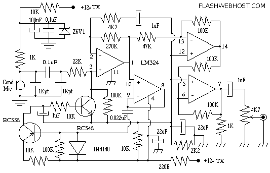
The microphone amplifier comprises an LM324 integrated circuit and two transistors. The LM324 is available in a 14-pin dual in-line package (DIP) and was acquired at a cost of Rs 6. It contains four identical operational amplifiers. The transistors...