
Jammer circuit

The design of the frequency jammer involves several critical components and considerations to ensure effective operation. The VCO, ZX95-2650, serves as the core element of the jamming circuit, generating the RF signal that interferes with wireless communication. The selection of this particular VCO was based on its tunability and performance characteristics, which are essential for effectively jamming signals in the 2.4 GHz band.
The triangle wave generator circuit is designed to produce a triangle wave with a precise frequency and amplitude. The operational amplifiers used in the circuit are configured to generate the desired waveform, with the DC offset and amplitude set by specific resistors. The triangle wave frequency is adjustable, allowing the operator to optimize the jamming effectiveness based on the modulation schemes of the targeted signals.
When implementing the jammer, care must be taken to avoid unintentional interference with other RF devices operating in adjacent frequency bands. Therefore, the design includes provisions for adjusting the frequency sweep range to ensure that only the intended signals are affected. Additionally, the performance of the jammer can be evaluated using a spectrum analyzer, which provides insight into the effectiveness of the jamming signal and allows for further refinements to the design.
Overall, the frequency jammer is a carefully engineered device that utilizes a combination of RF technology and circuit design principles to disrupt wireless communications in the 2.4 GHz frequency band. The effectiveness of the jammer depends on the precise control of the VCO and the triangle wave generator, making the understanding of these components vital for successful implementation.The frequency jammer works by creating interfering RF noise, centered around the 2. 45 GHz carrier. As the power associated with the noise increases, the signal to noise ratio for the wireless communication channel decreases. This increases the bit error rate until it becomes large enough for the wireless device to be no longer operable.
The freque ncy jammer is designed around the voltage controlled oscillator, VCO, which creates the interfering RF signal. While VCO`s can be built using opamps, resistors and capacitors, the low cost, availability and reliability of prefabricated VCO`s make it optimum to just purchase the device.
For our proof-of-concept design, we needed to create an interfering signal for the 2. 4 GHz band. We were able to find a VCO from Mini-circuits that met these requirements. The VCO, ZX95-2650, can be tuned from 2. 05 GHz to 2. 70 GHz and is already housed in a case with an SMA connector. The ZX95-2650 was a little more expensive than surface mount VCO`s, but fit within our budget and reduced the time we would need to design a Printed Circuit Board (PCB). The jammer works by applying a triangle wave to the input of the VCO. The voltage range of the triangle wave corresponds to an interfering frequency range of the VCO. Each prefabricated VCO will have a specific voltage range that corresponds to an interfering frequency range.
In the case of the ZX95-2650, we decided that a voltage range of 9. 6 V to 12. 5 V would create the desired interfering signal for our project. According to the data sheet of the VCO, this corresponds to the VCO being swept from about 2. 38 GHz to 2. 5 GHz. It is necessary to sweep the VCO from slightly below the 2. 4 GHz band to slightly above 2. 4 GHz in order to ensure the desired jamming takes place. Also note that if you sweep too broad of a frequency range you may interfere with RF signals that you did not intend to jam. The triangle wave schematic pictured in Figure 1 shows the triangle wave that was designed for this project.
It was constructed using basic opamps, capacitors and resistors. The applied voltage to the opamp sets the DC offset of the triangle wave. In this case we needed the DC offset to be 11V in order to sweep the VCO in the desired frequency range. The resistor, R2, controls the amplitude of the circuit. With the applied voltage setting the DC offset at 11V, we only needed small amplitude. In this case, the amplitude was about 1. 5 V. The resistor and capacitor, R1 and C1, adjust the frequency of the circuit. Figure 2 shows the output of the triangle wave generator. After the triangle wave generator was constructed we connected the VCO to a spectrum analyzer to confirm the output matched our expected results.
Figure 3 shows the VCO before the triangle wave generator was connected with a constant 12V applied to it. The figure illustrates that with a constant voltage the VCO will create an interfering signal, but the bandwidth is very small.
In Figure 4, the VCO has a triangle wave applied to it. This output sweeps from about 2. 2 GHz to 2. 5 GHz. Also note that there are instances when part of the range we are trying to jam, has no interfering signal in it. This is related to the frequency of the circuit. The VCO uses the triangle to sweep the small frequency range shown in Figure 3 across a broader frequency range as seen in Figure 4.
The slower the triangle wave oscillates the more time the VCO has to reach its peak power output, but this is a trade off because as the VCO sweeps at a slower rate there are more gaps in the interfering signal. The frequency of the triangle wave generator can be very important when designing a jammer depending on the type of signal modulation you are trying to block.
WiFi and Bluetooth both use the 2. 4 GHz range and these are the two types of signals we were trying to block. After designing the jammer, we ran into unexpected problem. WiFi and Bluetooth use two 🔗 External reference
Related Circuits
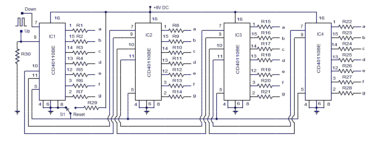
This circuit diagram illustrates a simple up/down counter suitable for various applications. It utilizes the CD40110BE IC, a CMOS decade up/down counter. Common cathode seven-segment displays are connected to the outputs of each IC. The display connected to IC1...
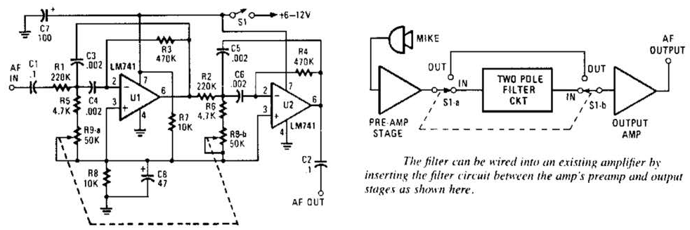
This variable-frequency audio bandpass filter is constructed using two 741 operational amplifiers connected in cascade. The two 741 op amps are configured as identical RC active filters and are cascaded to enhance selectivity. The filter's tuning range spans from...
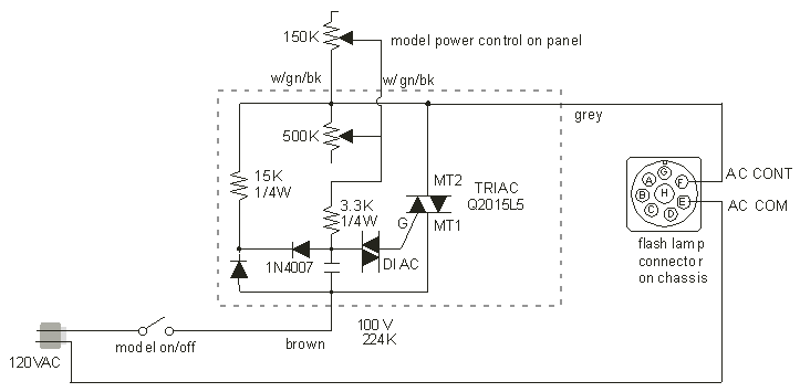
There are two independent modeling light circuits for the P2000D, one for each of the two channels. The modeling light circuit is completely separate from the high voltage strobe circuitry, even featuring its own On/Off switch. Therefore, the functionality...
Our programmable MP3 player has an interface to an LCD with a HD44780 controller. These are alphanumeric LCDs with one to 4 lines of text and 16 to 40 characters per line. However, these LCDs (and LCDs in general)...
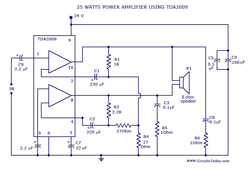
Power amplifier circuit diagram with schematics. This simple audio power amplifier circuit is designed for 25 watts output power using TDA 2009 IC, which has two channels (stereo), 12.5 W for each channel. The described power amplifier circuit utilizes the...
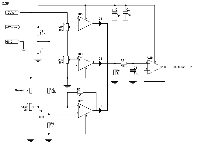
The circuit is designed to provide protection to a DIY switching power supply for car amplifiers by shutting down under any or all of the three modes of protection (over voltage, under voltage and over temperature) with minimal components. The...