
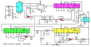
Moduler Preamplifier Circuit
This module's design emphasizes precision in audio control through the use of rotary switches, which provide a more reliable and accurate means of adjusting tone settings compared to traditional potentiometers. The asymmetrical configuration underscores the preference for boosting frequencies, aligning with common usage patterns in audio applications. The inclusion of specific dB steps for both bass and treble adjustments allows for tailored audio experiences, particularly in professional audio setups where precise sound reproduction is crucial.
The power supply design is straightforward, leveraging common components to generate the necessary dual-rail voltages. The selection of a center-tapped transformer simplifies the rectification process, while the use of smoothing capacitors ensures stable voltage levels for the operational amplifiers. The addition of integrated circuit regulators further stabilizes the output, ensuring consistent performance across various operating conditions.
In scenarios where the preamplifier is used as a stand-alone unit, the incorporation of output protection measures is critical to prevent damage from accidental short circuits. The use of a series resistor is an effective and low-cost solution, safeguarding the circuit without significantly impacting audio quality. Overall, this module's design reflects a careful balance between functionality, reliability, and ease of integration into existing audio systems.This Module employs an unusual topology, still maintaining the basic op-amp circuitry of the Main Module with a few changes in resistor values. A special feature of this circuit is the use of six ways switches instead of the more common potentiometers: in this way, precise "tone flat" setting, or preset dB steps in bass and treble boost or cut can
be obtained. Tone Control switches also allow a more precise channel matching when a stereo configuration is used, avoiding the frequent poor alignment accuracy presented by common ganged potentiometers. Six ways (two poles for stereo) rotary switches were chosen for this purpose as easily available. This dictated the unusual "asymmetrical" configuration of three positions for boost, one for flat and two for cut.
This choice was based on the fact that tone controls are used in practice more for frequency boosting than for cutting purposes. In any case, +5dB +10dB and +15dB of bass boost and -3dB and -10dB of bass cut were provided. Treble boost was also set to +5dB +10dB and +15dB and treble cut to -3. 5dB and -9dB. Those wishing to use common potentiometers in the usual way for Tone Controls may use the circuit shown enclosed in the dashed box (bottom-right of the Tone Control Module circuit diagram) to replace switched controls.
The Tone Control Module should usually be placed after the Main Input Module, and the volume control inserted between the Tone Control Module output and the power amplifier input. Alternatively, the volume control can also be placed between Main Input Module and Tone Control Module, at will.
Furthermore, the position of these two modules can be also interchanged. The preamplifier must be feed by a dual-rail, +24 and -24V 50mA dc power supply. This is easily achieved by using a 48V 3VA center-tapped mains transformer, a 100V 1A bridge rectifier and a couple of 2200 µF 50V smoothing capacitors. To these components two 24V IC regulators must be added: a 7824 (or 78L24) for the positive rail and a 7924 (or 79L24) for the negative one.
The diagram of such a power supply is the same of that used in the Headphone Amplifier, but the voltages of the secondary winding of the transformer, smoothing capacitors and IC regulators must be uprated. Alternatively, the dc voltage can be directly derived from the dc supply rails of the power amplifier, provided that both 24V regulators are added.
If this preamplifier is used as a separate, stand-alone device, thus requiring a cable connection to the power amplifier, some kind of output short-circuit protection is needed, due to possible shorts caused by incorrect plugging. The simplest solution is to wire a 3K3 1/4W resistor in series to the output capacitor of the last module (i.
e. the module having its output connected to the preamp main output socket). 🔗 External reference
Related Circuits
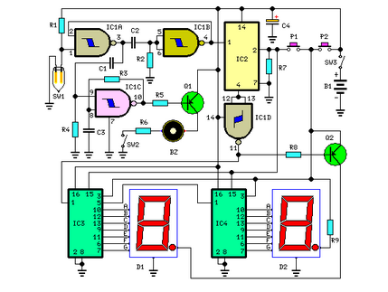
This circuit measures the distance covered during a walk. The hardware is housed in a small box that can be placed in a pocket, and the display is designed as follows: the leftmost display D2 (the most significant digit)...
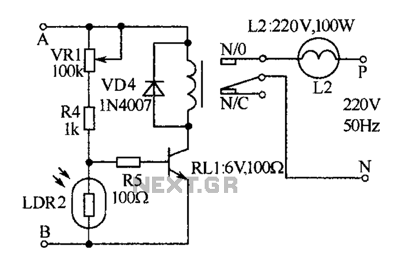
The receiver, as depicted in the figure, assists patients in avoiding missed audio signals during the daytime. The receiver operates independently, and the lighting will automatically turn off. At night, the lighting signal receiver activates simultaneously with the patient's...
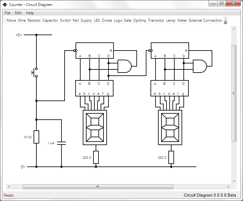
This is Circuit Diagram 0.1 Alpha Software, available for free download and open source. The Circuit Diagram 0.1 Alpha Software is designed as an intuitive platform for creating and editing electronic circuit schematics. It provides users with a variety of...
Magnetic pickups in musical instruments exhibit a relatively high output impedance, which can lead to a decrease in treble response when connected through long cable runs or to equipment with low input impedance. This preamplifier addresses these challenges by...
The following circuit illustrates a Cat and Dog Repellent Timer Circuit Diagram. Features include the capability to maintain a deep cycle battery charged by a solar panel. The Cat and Dog Repellent Timer Circuit is designed to provide a humane...
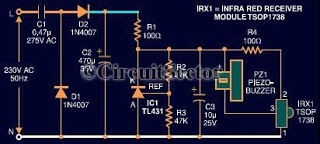
This document presents an infrared remote control tester circuit that can be constructed at a low cost. The circuit is built around the infrared receiver module TSOP1738. The state of the remote control can be observed through the sound...