
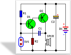
Monostable multivibrator schematic
The monostable multivibrator, commonly referred to as a one-shot timer, is a circuit that transitions from a stable state to a temporary unstable state when triggered. The primary function of this circuit is to produce a single output pulse of a specified duration in response to an input trigger.
In the schematic, typically, two transistors are used, where one is in an active state while the other is in a cutoff state upon circuit activation. The circuit is designed such that when a trigger pulse is applied, the conducting transistor allows current to flow through a load, generating an output pulse. The duration of this output pulse is determined by the RC time constant of the circuit, which consists of a resistor and capacitor connected in a specific configuration.
The monostable multivibrator differs from the astable multivibrator in that it does not oscillate between two states but rather returns to its stable state after the output pulse is generated. This is facilitated by the charging and discharging of the capacitor, which influences the timing of the output pulse. The circuit is particularly useful in applications requiring precise timing control, such as in timers, pulse-width modulation, and signal conditioning.
When designing the circuit, it is essential to select appropriate values for the resistor and capacitor to achieve the desired pulse width. The output pulse width (T) can be calculated using the formula T = 1.1 * R * C, where R is the resistance in ohms and C is the capacitance in farads. Understanding this relationship is crucial for tailoring the circuit to specific timing requirements in various electronic applications.The schematic for a monostable multivibrator is shown in figure 3-11. Like the astable multivibrator, one transistor conducts and the other cuts off when the circuit is energized. Recall that when the astable multivibrator was first energized, it was impossible to predict which transistor would initially go to cutoff because of circuit symmetry. The one-shot circuit is not symmetrical like the astable multivibrator. Positive voltag 🔗 External reference
Related Circuits
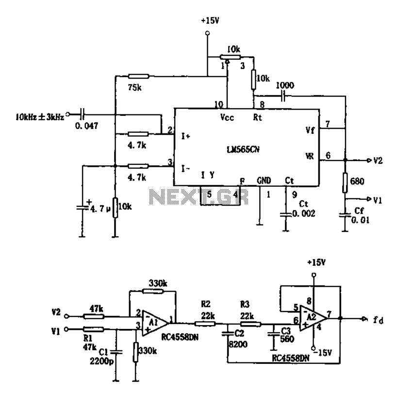
The circuit utilizes a 10 kHz and 3 kHz LM565CN to create an FM demodulation setup. The output diagram (b) illustrates the differential demodulation outputs V1 and V2 from the differential amplifier A1, which provides level displacement and amplification....
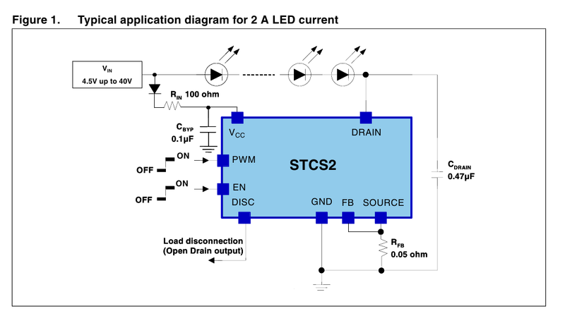
A driver based on the STCS2 for a 445nm laser is being developed. The STCS2 was selected due to its low voltage drop, and the power supply will consist of two lithium-ion cells. The STCS2 is a highly efficient, low-dropout...
In the 555 datasheet, there is a pulse width modulation circuit that resembles this one, with the only difference being that pin 5 is labeled as 'audio'. The 555 timer IC is a versatile device commonly used in various applications,...
This circuit, housed in a compact plastic enclosure, is designed for portability and can easily fit into a bag or handbag. A small magnet is positioned near a reed switch and is attached to the individual carrying the bag...
This chapter presents a variety of circuits for basic power supplies, including both line-powered and inverter types, some of which feature regulators, modulation inputs, and additional functionalities. Several circuits have been reverse-engineered from actual commercial products, and others, designed...
This circuit is designed to signal the exceeding of a fixed threshold in room noise through a flashing LED. Three fixed levels are selectable: 50, 70, and 85 dB. Two operational amplifiers provide the necessary gain for sounds captured...