
555 monostable pulse width modulator

The 555 timer IC is a versatile device commonly used in various applications, including pulse width modulation (PWM) circuits. In the context of PWM, the 555 timer can effectively control the duty cycle of a signal, which is essential for applications such as motor speed control, light dimming, and audio signal modulation.
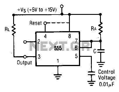
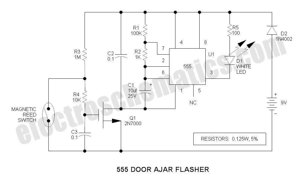
In the described circuit, the 555 timer operates in astable mode, generating a continuous square wave output. The frequency and duty cycle of this output can be adjusted by varying the resistances and capacitance connected to the timer. The circuit typically includes two resistors (R1 and R2) and a capacitor (C1) connected to the discharge (pin 7), threshold (pin 6), and trigger (pin 2) pins of the 555 timer.
In this specific configuration, pin 5 is designated for audio modulation, allowing the circuit to modulate audio signals based on the PWM output. This can enhance sound quality and control over audio devices. The audio signal can be introduced at this pin, which may influence the timing characteristics of the PWM output, enabling dynamic sound modulation.
It is crucial to ensure proper component selection to achieve the desired frequency and duty cycle. The resistor values, in combination with the capacitor, determine the oscillation frequency according to the formula:
\[ f = \frac{1.44}{(R1 + 2R2)C1} \]
Where 'f' represents the frequency in Hertz, 'R1' and 'R2' are the resistance values in ohms, and 'C1' is the capacitance in farads.
Overall, the integration of an audio modulation feature at pin 5 enhances the functionality of the 555 timer in PWM applications, making it suitable for a variety of electronic projects that require precise control over signal characteristics.In the 555 datasheet they have a pulse width modulation circuit similar to this with the only difference being that they have pin 5 labelled as `audio .. 🔗 External reference
Related Circuits
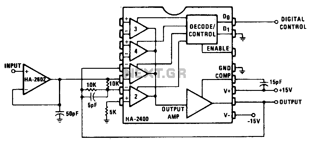
This circuit transmits the input signal at unity gain, either in its original form or inverted, based on the digital control input. A buffered input is utilized, as low source impedance is crucial. Gain can be introduced through modifications...
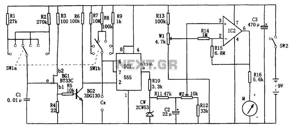
The circuit illustrated in Figure 555 represents a DC capacitor tester. This tester includes a pulse generator, a single-shot circuit, and a head indicating DC amplifier circuit. It is capable of measuring capacitance in the range of nanofarads (nF)...
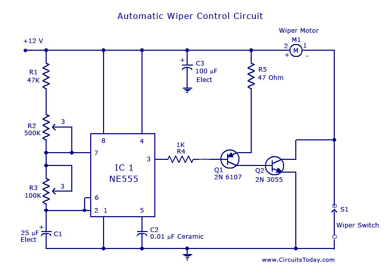
A circuit for car windshield/wiper motor speed control built using an NE 555 IC. This enables intermittent windshield wiper control, which changes the sweep rate to 10 seconds. The circuit utilizes the NE 555 timer IC configured in astable mode...
In this mode, the timer operates as a one-shot device. The external capacitor is initially kept discharged by a transistor internal to the timer. When a negative trigger pulse is applied to pin 2, the flip-flop is set, causing...
This pulse generator utilizes a single integrated circuit (IC) and six passive components to achieve a frequency range of 400 to 4000 Hz, with an adjustable duty cycle ranging from 1% to 99%. The circuit employs a threshold detector...
This is a compact LED flasher circuit designed using the 555 timer integrated circuit (IC), powered by two 1.5V batteries. The circuit can function as a flashing metronome, dark room timer, reminder, or for other similar applications. In the...