
More DIY IR Jammer
A DIY infrared jammer circuit can be designed using a TL082 operational amplifier, which is a low-noise JFET-input op-amp suitable for audio and low-frequency applications. The circuit typically consists of a feedback loop that generates oscillations at a frequency that interferes with IR remote signals. The TL082's characteristics allow for stable oscillation and precise control over the output frequency.
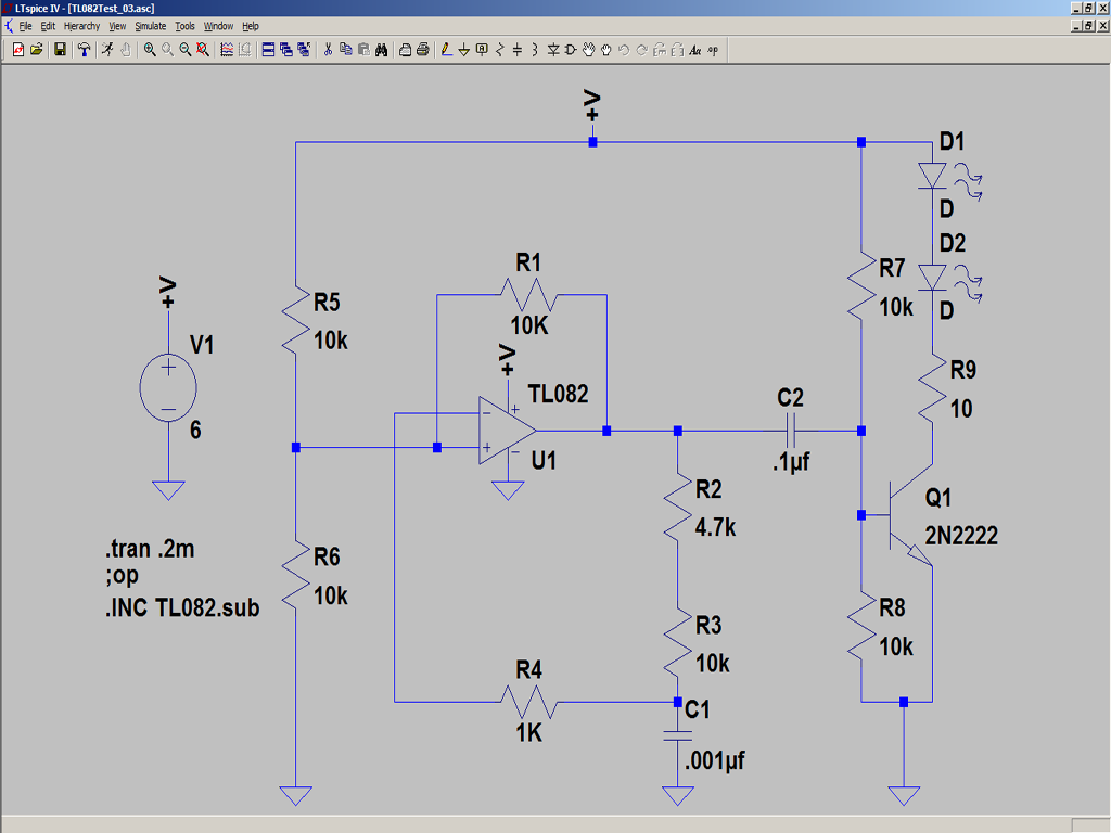
The circuit schematic would include the TL082 configured in an astable multivibrator arrangement, where the timing components, typically resistors and capacitors, determine the oscillation frequency. The output from the op-amp would drive a series of infrared light-emitting diodes (LEDs), which emit IR pulses that can disrupt the communication between a remote control and its target device.
The power supply, set to 6 volts, is connected to the circuit to ensure that the op-amp and IR LEDs operate efficiently. The use of a breadboard facilitates easy adjustments and modifications to the circuit, allowing for experimentation with component values to achieve the desired output frequency.
Testing the circuit involves using a video camera or a photodiode connected to an oscilloscope to verify that the IR LEDs are emitting pulses. The photodiode's output can be observed on the oscilloscope, displaying the pulse train generated by the circuit. This method provides a visual confirmation of the circuit's functionality.
In practical applications, the IR jammer can be used to block signals from remote controls, effectively disabling their functionality. However, caution should be exercised, as the use of jammers may be subject to legal restrictions depending on the jurisdiction.Breadboard and test the DIY IR jammer last weekend but it`s taken me this long to carve out a minute to post the results. The schematic is correct and only took a few minutes to re-create on the plugboard. For power I used a small bench supply set to 6 volts to duplicate four AA cells. When I powered up the circuit it oscillated just as pred icted, but the frequency of oscillation did not agree with LT Spice. The first time I entered in the schematic I just picked an arbitrary Op Amp from those provided by Linear Technology. That is what caused the discrepancy. I tracked down a TL082 model and that provided results that are nearly identical to the actual circuit.
Here is a screen shot of the LT Spice schematic including the spice directives used to add the external model. So the lesson here is use the correct model for accurate results. I`m including the TL082 model I used in the body of the post. Just copy and paste it into a text file adding a. sub extension if you want to do your own simulation. I came up with two simple tests to confirm that the circuit was actually emitting infrared pulses. The first test was to simply point a video camera at the LEDs while the circuit was on. This picture shows this basic setup. The next test was equally as easy and simply involved attaching a photodiode to an oscilloscope, and then pointing that photodiode at the IR LEDs.
The resultant pulses can be easily seen here. I took the lab supply with the plugboard on top into the living room and set it on the coffee table and flipped the power supply switch on. Admittedly my setup is not very covert, but it did successfully disable the remote`s ability to change channels.
🔗 External reference
Related Circuits
After completing several V-USB tutorials, the next project undertaken was to create a compact USB HID keyboard device that types a password stored in EEPROM each time it is connected. The password can be regenerated by pressing the CAPS...
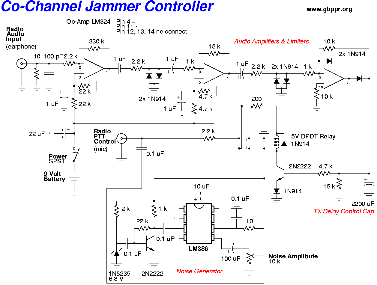
A barrage noise jammer for VHF/UHF communications is constructed using an old TV tuner. The local oscillator of the tuner is tapped and amplified. The voltage tuning line of the tuner is combined with a sweeping, random noise signal. The...
This circuit is designed to disrupt infrared (IR) remote signals, allowing users to override volume settings on a stereo, change TV channels, or create general interference. Key components include a ceramic capacitor, an electrolytic capacitor, a resistor, a battery,...
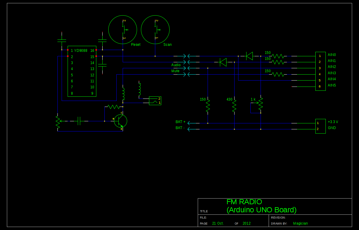
A local convenience store (Dollarama in Montreal, Canada) offers an appealing FM radio for just $3. The idea of interfacing this radio with an Arduino presents a fun challenge. Although the primary goal is not to create a radio,...
The IR Jammer is a fun project that provides a bit of safe, non-destructive fun. The Infrared Remote Control Jammer allows you to render all IR remote controls inoperative! The microcontroller in this design allows for all 6 of...
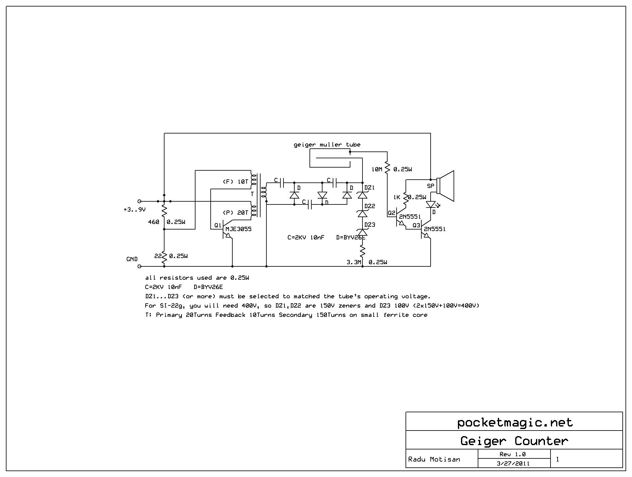
The recent events in Fukushima, Japan, raised significant concerns regarding radiation levels. In response to public demand, a simple Geiger-Muller counter has been designed using the Russian tube SI-22G and a single transistor-regulated inverter that outputs 400V, which is...