
DIY Arduino FM Radio Shield

The project involves creating a simple interface between the FM radio and an Arduino microcontroller, utilizing the YD9088 IC for radio functionality. The radio's straightforward user interface consists of two buttons that control station scanning and power. The integration process begins with careful soldering to the radio's surface mount components, specifically connecting to pins 15 and 16 for button interfacing. The Arduino will provide power via its onboard voltage regulator, which simplifies the setup by eliminating the need for battery power.
To ensure proper operation, a potentiometer is used to fine-tune the voltage level at the Scan input of the IC, which is critical for reliable station changes. The project requires attention to detail in soldering and voltage adjustments, as the IC's sensitivity to input levels can lead to erratic behavior if not correctly managed. Additionally, the use of an audio jack as an antenna is essential for optimal radio reception, as the radio relies on external wires to capture radio signals effectively.
Overall, this project serves as an engaging way to explore interfacing techniques between an inexpensive FM radio and an Arduino, while also providing insights into the functionality of radio circuits and the importance of precise voltage control in electronic designs.I`ve been visiting local convenience store (Dollarama, here in Montreal, Canada) and notice nice looking FM Radio, just for only $3. Why not to try to interface it to my lovely Arduino Idea looks quite challenging, the same time what is the point in interfacing a DSP radio shield to arduino I don`t need a radio, I want to have fun experimenting
with it, so lets go to the bare metal! You, probably, could find the same or very similar radio all around the globe, with two buttons user interface, powered by two AAA or one CR2032 coin battery (like in my case), and low price. Hardware design based on IC TDA7088 (depending on the manufacturer, may be clones SC1088, SA1088, CD9088, D7088, or YD9088).
My radio has YD9088 inside. Quick search on a Google, brings a data sheet. I`d say, It`s not very informative, but at least it shows basic application circuit. The most difficult part of this project, is soldering to surface mount radio components. In minimum configuration just two wires, interfacing two front-panel buttons. (Other two, for powering up the radio from arduino +3. 3 V on-board voltage regulator instead of battery, should be much easier to attach). I solder wires to the caps, on the side, which connected to the pins 15 and 16 of the IC. In this case, there is minimum impact on usability of the radio, as buttons were not touch. May be important for debugging. If your soldering skills are not as good as mine, you could solder to the traces, removing buttons. On the pictures below you would find two more wires, attached to pin 1 and to earphone`s jack-connector, but they are not in use in this project, and you could left them out. If you look at the electrical drawings of the shield, you would notice 1 k pot. I build a first version using just two resistors divider, as it shown in Reset signal line. But it turns out, that IC is quite capricious for the voltage level it senses on the Scan input. On some occasions, it refused to change a station, and in some it flipped to reset . Trim the pot, to get voltage at pin 15 about 3. 1 3. 2 V. It would be easy to measure voltage with DMM, temporary changing delay in this section of the code: to 10000 or even 20000.
You may need something to be plugged in the earphones jack, as radio is using wires like an antenna. Headphones, or USB speakers cable, works quite well. BTW, the default value 50 may not be enough to push a radio up with strong RF signal. Try to send a few s simultaneously, ss or ssss . Setting delay higher than 50 is not recommended, as jump may be to wide, so you likely to miss something interesting in broadcasting. 🔗 External reference
Related Circuits
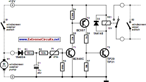
Most recent cars are equipped with a significant amount of electronics, including ABS brake systems, engine control with injection calculators, airbag activation, and various comfort functions. One such function, which is often overlooked, is the automatic activation of windshield...
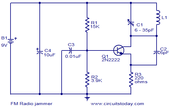
The circuit presented here can be used to jam FM radios in its vicinity. It consists of a classic single transistor oscillator operating in the VHF region. The working principle of the circuit is straightforward: powerful VHF oscillations from...
The crock pot is connected to a relay that can turn it on or off. The relay is controlled by a microcontroller based on readings from a temperature sensor (thermistor) located inside the crock pot. The objective is to...

This is a 1 watt FM amplifier with a robust design that can be used to amplify an RF signal in the 88 to 108 MHz band. It is highly sensitive when utilizing quality RF power amplifier transistors, trimmers,...
This circuit demonstrates the use of Silicon Controlled Rectifiers (SCRs) to control low-voltage pulsating DC for operating homemade LED light panels. Although the circuit utilizes an Arduino, the underlying concepts are applicable to various microcontrollers, whether through hardware interrupts...
The entire system was constructed within a package measuring approximately 70mm x 96mm x 30mm. This package housed the Terminal Node Controller (TNC), transmitter, interface circuitry, and a lithium battery capable of sustaining approximately 20 hours of continuous operation....