
mosfet Driving LED strip from microcontroller
To control a high-current LED strip using a microcontroller, a common approach involves utilizing a MOSFET as a switch. Given the LED strip's current requirement of approximately 1.5A at 12V, it is crucial to select a MOSFET that can handle this load efficiently. Many MOSFETs require a gate-source voltage (Vgs) higher than 3.3V to achieve full enhancement mode and minimize on-resistance, which can lead to overheating and inefficiency.
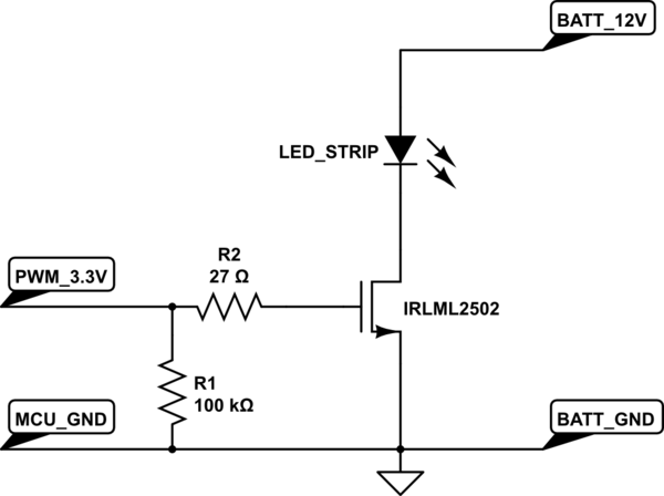
In this scenario, employing a small NPN transistor as a level shifter is a practical solution. The NPN transistor can be used to control the gate of the MOSFET by switching 12V to the gate when the microcontroller outputs a PWM signal. This configuration allows the microcontroller to control the LED strip without directly driving the high gate voltage required by the MOSFET.
The circuit can be designed as follows:
1. Connect the microcontroller's PWM output to the base of the NPN transistor through a current-limiting resistor, typically in the range of 1kΩ to 10kΩ.
2. The collector of the NPN transistor should be connected to the gate of the MOSFET, while the emitter is connected to ground.
3. A pull-down resistor (10kΩ) should be placed between the gate of the MOSFET and ground to ensure the MOSFET turns off when the NPN transistor is not conducting.
4. The source of the MOSFET is connected to ground, and the drain is connected to the negative terminal of the LED strip. The positive terminal of the LED strip is connected to the +12V supply.
When the microcontroller outputs a high signal, the NPN transistor turns on, allowing 12V to be applied to the gate of the MOSFET, thus turning it on and allowing current to flow through the LED strip. When the PWM signal is low, the NPN transistor turns off, deactivating the MOSFET and turning off the LED strip.
This setup not only allows for efficient control of the LED strip but also protects the microcontroller by isolating it from the higher voltage levels present in the circuit. For component recommendations, suitable NPN transistors might include the 2N3904 or BC547, while MOSFET options could include the IRF520 or IRL540, which are known for their ability to handle higher currents and lower gate thresholds.A strip of LEDs from a microcontroller using PWM to control the brightness. The strip I have takes about 1. 5A at 12V. I`m only familiar with purely low power digital electronics so wanted to check if these assumptions are correct and get any advice :- However looking at the spec of the various MOSFETs I can buy it looks like any that can pass this amount of current require considerably more than 3. 3v I can get from my microcontroller to turn on fully. So am I best to have a small NPN transistor switching 12v to the input of a mosfet to control the actual LED strip (Sorry I can`t draw a diagram on this computer but can add one later if needed) Are my assumptions correct, and does anyone have any advice or a better way I`d also be interested in recommendations for suitable parts although that`s not my main question. (Edit: I looked for other posts that answered this and didn`t find anything that was quite what I wanted, if someone has a link to a duplicate then please post it and I`ll happily close the question).
🔗 External reference
Related Circuits
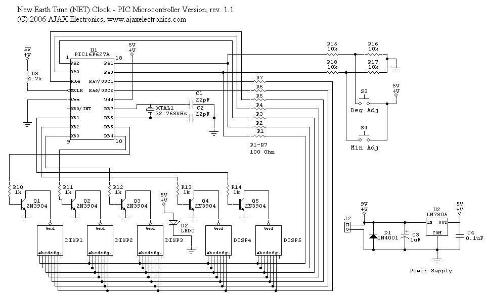
The schematic diagram and electronic assembly are relatively simple, as most of the functionality is managed by the microcontroller code. The schematic diagram serves as a visual representation of the electronic circuit, outlining the connections between various components such as...
The transformer is a 220V to 12V, 50Hz, and 3.6VA PCB type transformer. The model depicted is HRDiemen E3814056. Being encapsulated, it is isolated from external influences. A 250V 400mA glass fuse protects the circuit from damage caused by...
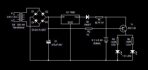
This is a high-efficiency emergency lamp that utilizes high-brightness white LEDs. It automatically activates during power failures and deactivates when power is restored. The emergency lamp circuit is designed to provide reliable illumination during power outages, utilizing high-brightness white LEDs...
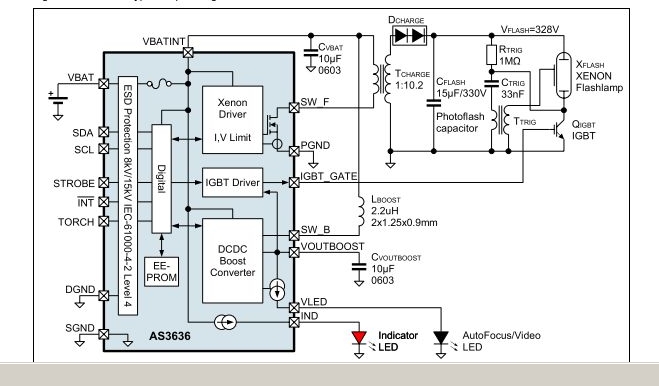
The AS3636 is a highly integrated photoflash charger that includes an IGBT driver, an inductive DC-DC boost autofocus/video LED driver, an indicator LED driver, and incorporates system-level ESD protection. The AS3636 is designed for efficient photoflash charging applications, providing a...
Any step-down DC-DC converter can be utilized as an inverter without modifications to the operating schematic. The only differences between the standard step-down application and the inverting operation are the labels of the connection points. The step-down VOUT is... A...
A voltage-controlled oscillator (VCO) is an electronic signal generator that produces a signal with a variable frequency, which is dependent on an input voltage level. A voltage-controlled oscillator is a fundamental component in various electronic applications, including phase-locked loops (PLLs),...