
PIC Controlled Relay Driver
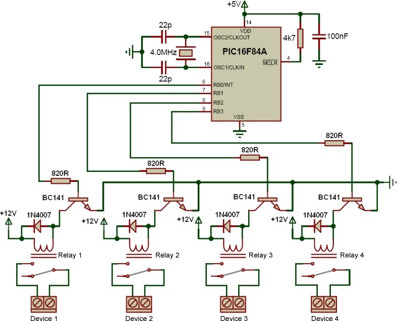
The described circuit utilizes a PCB-type transformer to step down the voltage from 220V AC to 12V AC, operating at a frequency of 50Hz. The encapsulation of the transformer provides essential isolation, ensuring that external electrical interference does not affect the operation of the circuit. The inclusion of a 250V 400mA glass fuse is critical for circuit protection, as it prevents potential damage from excessive current that may arise from faults or overload conditions.
To address potential high amplitude signals generated by high-power devices connected to the same line, a varistor is deployed in parallel with the input. This component effectively clamps voltage spikes, providing a safeguard against transient overvoltages. The line filter configuration is designed to reduce electromagnetic interference (EMI) and high-frequency noise that can adversely impact circuit performance. The choice between common mode and differential mode filtering is dictated by the specific application and the nature of the noise present.
The filtering section is equipped with two unpolarized 100nF capacitors rated for 630V, strategically placed to maximize their effectiveness. These capacitors are vital in diminishing high-frequency noise due to their decreasing capacitive reactance at elevated frequencies. The bridge rectifier, composed of 1A diodes, converts the AC signal to a pulsating DC, which is then smoothed by the 2200 µF capacitor, ensuring a stable output voltage for downstream components.
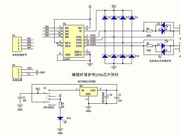
The microcontroller employed, the PIC16F84A, orchestrates the operation of the circuit by controlling the relays through NPN transistors. The relays are connected to specific pins on the microcontroller, allowing for precise control over their activation. The use of BC141 transistors facilitates this control, but care must be taken to manage reverse EMF generated when the transistors switch off. The inclusion of 1N4007 diodes provides a necessary protective measure, preventing damage to the transistors from back EMF.
Radially mounted resistors within the circuit serve various functions, including current limiting and voltage division, critical for ensuring proper operation of the microcontroller and associated components. The project file includes example C and HEX code files, which are essential for programming the microcontroller to energize the relays at specified intervals, in this case, every five seconds, thereby enabling timed control of connected devices. This comprehensive design effectively combines power management, signal conditioning, and control logic to create a robust electronic system.The transformer is a 220V to 12V, 50Hz and 3. 6VA PCB type transformer. The model seen in the photo is HRDiemen E3814056. Since it is encapsulated, the transformer is isolated from the external effects. A 250V 400mA glass fuse is used to protect the circuit from damage due to excessive current. A high power device which is connected to the same lin e may form unwanted high amplitude signals while turning on and off. To bypass this signal effects, a variable resistor (varistor) which has a 20mm diameter is paralelly connected to the input. Another protective component on the AC line is the line filter. It minimizes the noise of the line too. The connection type determines the common or differential mode filtering. The last components in the filtering part are the unpolarized 100nF 630V capacitors. When the frequency increases, the capacitive reactance (Xc) of the capacitor decreases so it has a important role in reducing the high frequency noise effects.
To increase the performance, one is connected to the input and the other one is connected to the output of the filtering part. After the filtering part, a 1A bridge diode is connected to make a full wave rectification. A 2200 uF capacitor then stabilizes the rectified signal. The PIC controller schematic is given in the project file. It contains PIC16F84A microcontroller, NPN transistors, and SPDT type relays. When a relay is energised, it draws about 40mA. As it is seen on the schematic, the relays are connected to the RB0-RB3 pins of the PIC via BC141 transistors.
When the transistor gets cut off, a reverse EMF may occur and the transistor may be defected. To overcome this unwanted situation, 1N4007 diodes are connected between the supply and the transistor collectors. There are a few number of resistors in the circuit. They are all radially mounted. Example C and HEX code files are included in the project file. It energizes the next relay after every five seconds. 🔗 External reference
Related Circuits
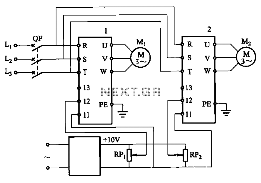
Adjust the potentiometers RPi and RPz to modify the speed of two motors. The circuit utilizes two potentiometers, designated as RPi and RPz, to control the speed of two separate motors. Each potentiometer is connected in a voltage divider configuration,...
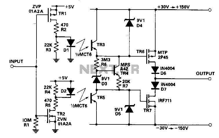
This circuit accepts a signal from a 5-V CMOS logic circuit and produces a high voltage of the same polarity. The high-voltage supply can be adjusted between ±30 V and ±150 V without requiring any changes to the circuit...
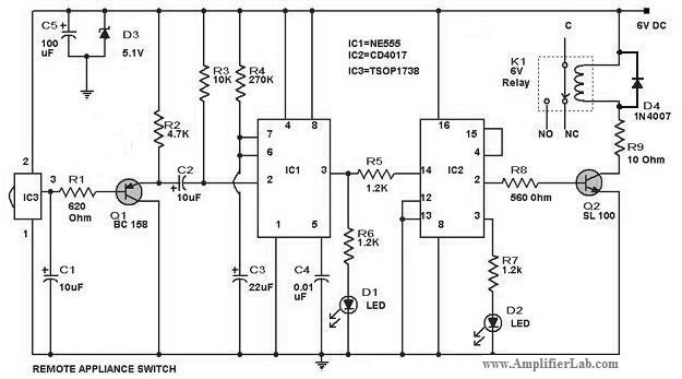
The circuit diagram of a remote-controlled appliance switch circuit includes two main components: IC1 (NE 555) and IC2 (CD 4017). The remote-controlled appliance switch circuit is designed to allow users to control electrical appliances wirelessly. The heart of this circuit...
Arduino can drive various types of motors. However, the low-power signals from Arduino must control high-power circuits to operate the motors effectively. This document will provide examples of how Arduino can control different motor types and sizes. A motor...
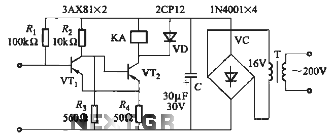
When the input is disconnected, the transistor VTi conducts, while VTz is in cutoff, causing relay KA to release. When the input is shorted, VTi is cut off, VTz conducts, and relay KA is activated. In this circuit configuration, the...

These novel relay driver circuits have the capability to activate a relay with a coil voltage rating that is double the supply voltage (Vcc). Once the relay is activated, the armature is maintained using Vcc, resulting in a significant...
Warning: include(partials/cookie-banner.php): Failed to open stream: Permission denied in /var/www/html/nextgr/view-circuit.php on line 713
Warning: include(): Failed opening 'partials/cookie-banner.php' for inclusion (include_path='.:/usr/share/php') in /var/www/html/nextgr/view-circuit.php on line 713