
MOSFET Tester circuit

The circuit described is a specialized astable multivibrator designed for testing N-channel MOSFETs, such as the IRF830. The operation of the circuit hinges on the ability of the MOSFET to switch on and off, which is indicated by the flashing of an LED. The astable multivibrator configuration allows for continuous oscillation, generating a square wave output that can be used to drive the LED.
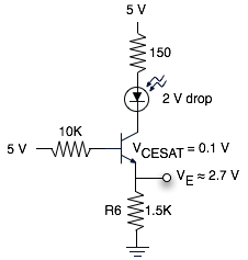
In the circuit, the astable multivibrator is constructed using two transistors, one of which is an NPN transistor. This NPN transistor is utilized as a common emitter buffer, which serves to amplify the signal from the drain of the MOSFET. The transistor's base receives pulses that indicate whether the MOSFET is functioning correctly. When the MOSFET is operational, it will allow current to flow, causing the LED to flash in response to the oscillations generated by the astable multivibrator.
The choice of the NPN transistor is flexible, as nearly any standard NPN transistor can be employed in this configuration, making the circuit cost-effective. The simplicity of the design allows for easy construction and troubleshooting, as well as the ability to test a wide range of MOSFETs. However, it is important to note that this circuit may not be capable of identifying all fault conditions in MOSFETs, as it primarily indicates whether the device is conducting or not.
Overall, this astable multivibrator circuit serves as a practical tool for quickly assessing the functionality of N-channel MOSFETs, providing a visual indication of their operational status through the LED.This is a variation on the astable multivibrator. Circuit was recently developed to test for N-mosfets(the power kind e.g irf830). I don?t claim circuit can test all bad mosfets or all fault mosfet conditions. If mosfet is working it will operate in the astable multivibrator circuit causing the Led to flash. A bad mosfet will not cause the LED to flash. Below is the circuit diagram, the other half of the astable utilizes an npn transistor to make the circuit cheap. Almost any npn transistor will work in this circuit. The npn transistor to the right is used as a common emitter buffer that also drives the led as it receives pulses from the mosfet drain.
🔗 External reference
Related Circuits
The 555 timer on the right is configured as an alarm sound generator, while the second 555 timer on the left functions as a 1 Hz astable multivibrator. The output from the left timer modulates the frequency of the...

This is a design schematic for sensing the electromagnetic field. The circuit is built using a 741 operational amplifier (op-amp) IC. It can detect electromagnetic fields, including those from hidden wiring. A 1mH inductor is employed for sensing the...
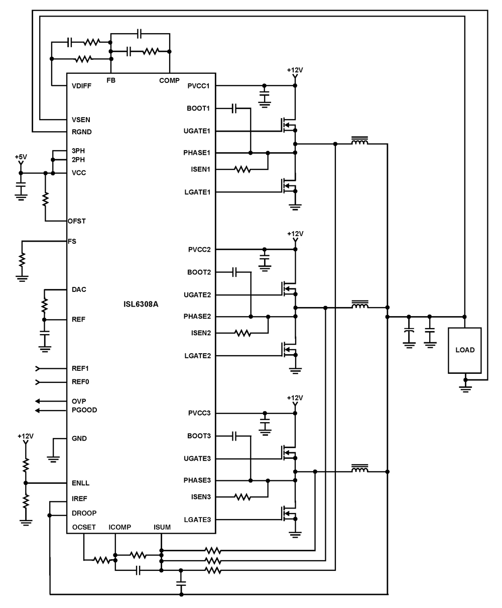
The ISL6308A is a three-phase PWM control integrated circuit (IC) equipped with built-in MOSFET drivers. It delivers precise voltage regulation suitable for various applications, including high current low voltage point-of-load converters, embedded systems, and other general low voltage medium...

A battery voltage indication circuit that changes the status display. When the battery voltage is normal, an additional transistor drives an LED, which remains off. However, if the battery voltage falls below a critical threshold, the LED begins to...
The schematic represents a relatively simple transistor circuit. Analyzing such schematics evokes memories of college days spent studying electrical engineering. However, the complexity of the schematic can be daunting after a long time away from the subject. To refresh...

This is a simple servo tester designed to thoroughly evaluate the capabilities of nearly any modern servo. It features two pushbuttons, labeled CENTRE and SWEEP, along with a potentiometer that functions in the following manner: The servo tester circuit is...