
Battery voltage indication circuit
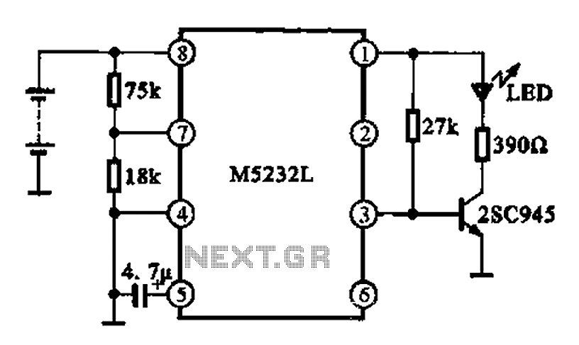
This battery voltage indication circuit is designed to monitor the voltage level of a battery and provide a visual alert through an LED indicator. The circuit typically consists of a voltage divider network, a comparator, a transistor, and an LED.
The voltage divider is formed by two resistors connected in series across the battery terminals. This divider reduces the battery voltage to a level suitable for comparison. The output from the voltage divider is fed into a comparator, which is configured to compare the divided voltage against a predetermined reference voltage. This reference voltage is set to correspond to the critical battery voltage level.
When the battery voltage is above the critical threshold, the output of the comparator remains high, keeping the transistor in the off state. Consequently, the LED remains unlit, indicating that the battery voltage is normal. Conversely, when the battery voltage drops below the critical level, the comparator's output switches low, turning on the transistor. This action allows current to flow through the LED, which then begins to flash, signaling that the battery is low and requires attention.
The flashing behavior of the LED can be achieved by incorporating additional components, such as a capacitor and a resistor, to create a timing circuit that controls the on-off cycling of the LED. This feature enhances the visibility of the low battery condition, making it more noticeable to the user.
Overall, this circuit provides a simple yet effective method for monitoring battery voltage and ensuring timely awareness of low battery conditions through visual signaling. Battery voltage indication circuit Using this circuit can change the status display, if foot plus a further transistor drive LED, the battery voltage is normal. LED is not lit, and when the battery voltage falls below a critical value, LED begins to flash indicating that the circuit shown
Related Circuits
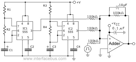
This circuit combines the outputs from two distinct 555 multivibrators using a summing operational amplifier (Op Amp). It serves to illustrate an alternative implementation of a 555 timer, with most background calculations addressed in other sections. The standard configuration...

The application circuit operates the device as illustrated below, allowing for intermittent lighting in specific situations (e.g., during surgery). It utilizes an LCE module for blackout emergency lighting, which activates automatically after a power failure, ensuring uninterrupted illumination. In...

The common characteristic of all previous low-power FM transmitters built over the decades is that their operating frequency is determined by an LC resonant circuit. Some of these transmitters exhibited excellent stability, while others did not; however, there has...

This amplifier circuit is designed to enhance TV signals in the UHF range. It employs a low-noise transistor, providing an amplification of 10 to 15 dB within the frequency spectrum of 400 MHz to 850 MHz. It is crucial...
The power supply has been simplified. Power transformers and rectifiers have been omitted, and some components from the MOSFET voltage regulator circuits have been removed, including 1N5242 zener diodes between the source and gate and 10k resistors in series...

This page presents a circuit featuring twenty open collector outputs that activate sequentially in a continuous, unidirectional loop. The circuit utilizes the 74LSxx family of TTL integrated logic devices. It is designed to drive light-emitting diodes or low current,...
Warning: include(partials/cookie-banner.php): Failed to open stream: Permission denied in /var/www/html/nextgr/view-circuit.php on line 713
Warning: include(): Failed opening 'partials/cookie-banner.php' for inclusion (include_path='.:/usr/share/php') in /var/www/html/nextgr/view-circuit.php on line 713