
Motor Speed control with optocoupler

This circuit description outlines the operational procedures for a remote-controlled system that utilizes a transmitter and receiver setup, typically found in RC vehicles or drones. The system functionality hinges on the correct sequence of actions to ensure safe operation and prevent damage to the components.
The initial step involves connecting a battery to the circuit; however, this should only be done when a jumper is in place. The jumper acts as a safety feature, preventing unintended activation of the system during setup. It is critical that the transmitter is powered on before proceeding with any further actions. This ensures that the control signals are active and ready to communicate with the receiver.
The throttle must be set to the "power off" position initially. This precaution prevents any unintended movement of the vehicle or drone during the setup phase, which could lead to accidents or damage. After confirming these settings, the jumper can be safely disconnected, allowing for the battery to be connected.
Once the battery is connected, the transmitter should be powered on again. At this point, the throttle can be adjusted to the "full power" position. This action enables the full operational capabilities of the system, allowing for responsive control of the vehicle or drone.
It is essential to follow these steps meticulously to ensure the safety and functionality of the electronic system. Any deviation from this procedure could result in malfunction or potential hazards.For normal use it`s necessary to connect the battery, when the jumper is connected. Please take care, that the transmitter is on and the throttle is set to "power off". * switch on the transmitter, throttle to power off * disconnect the Jumper, connect the battery * switch on the transmitter, thottle to full power 🔗 External reference
Related Circuits
This circuit diagram can be utilized to adjust the speed of a low-power induction motor, commonly found in fan applications. The circuit for controlling the speed of a low-power induction motor typically employs a variable frequency drive (VFD) or a...
The Star Delta starting method is a motor starting mechanism that minimizes the large amount of starting current drawn by motors. As the name suggests, the Star Delta method involves supplying the motor with 1/sqrt(3) (approximately 58%) of the...
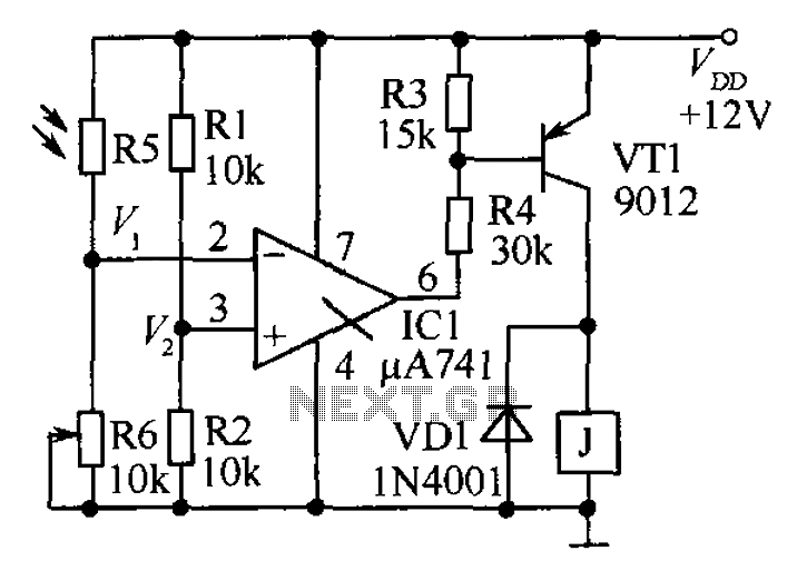
The circuit functions as a precision bright light control circuit, operating independently of power supply voltage and ambient temperature. Resistors R1, R2, R6, and the photosensitive resistor R5 form a two-arm Wheatstone bridge. The precision bright light control circuit utilizes...
This Project is used to control a single phase Motor from any where in the world through the telephone. The circuit consists of a DTMF tone detector and a powerful 8 bit Microcontroller AT89S52. The Microcontroller senses the DTMF...
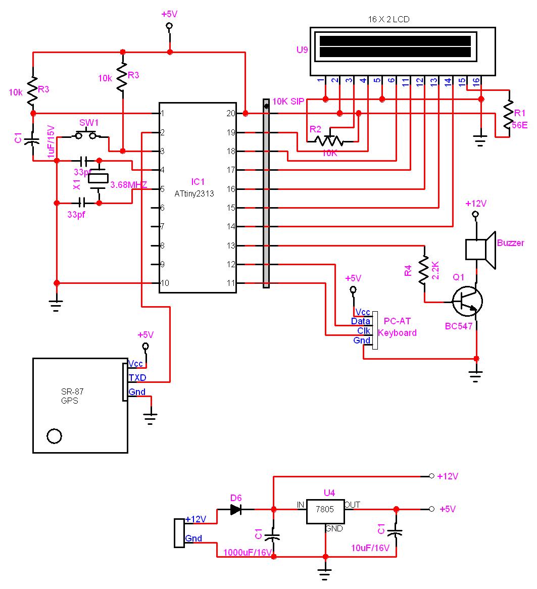
In this project, a GPS module is interfaced with an AVR microcontroller. The ATtiny2313 retrieves location data from the GPS and displays it on an LCD screen. The project involves the integration of a GPS module with the ATtiny2313 microcontroller,...
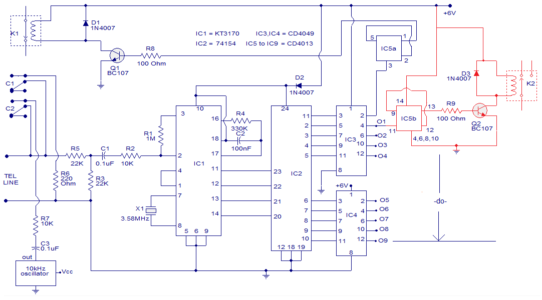
The circuit is a remotely operated DTMF telephone system capable of controlling up to nine devices using the keys 0 to 9 on a phone. The digit 0 is utilized to switch between the phone system remotely and alter...