
Synchronized TRIAC for Small Induction Motor Speed Control

The circuit for controlling the speed of a low-power induction motor typically employs a variable frequency drive (VFD) or a phase control method. In this application, a triac or a solid-state relay may be used to modulate the power supplied to the motor. The key components in the circuit include a microcontroller or a potentiometer for setting the desired speed, a triac for switching the motor on and off, and necessary protection components such as fuses and diodes to prevent damage from voltage spikes.
The microcontroller can be programmed to adjust the duty cycle of the signal sent to the triac, thereby controlling the effective voltage and frequency supplied to the motor. This modulation results in varying speeds of the motor, allowing for precise control based on the application requirements.
In addition, feedback mechanisms can be implemented to monitor the motor's speed and adjust the control signals accordingly. This can enhance performance and efficiency, particularly in applications where speed regulation is critical. The design should also incorporate heat sinks or cooling mechanisms to dissipate heat generated by the triac during operation, ensuring reliability and longevity of the circuit.
Overall, the circuit design should prioritize safety and efficiency, with appropriate ratings for all components to handle the expected load and environmental conditions. Proper layout and grounding techniques should be employed to minimize noise and interference, which can affect the operation of the motor and the overall performance of the system.We can use this circuit diagram to adjust the speed of a low-power induction motor, such as those which can be found in fan application. The function of. 🔗 External reference
Related Circuits
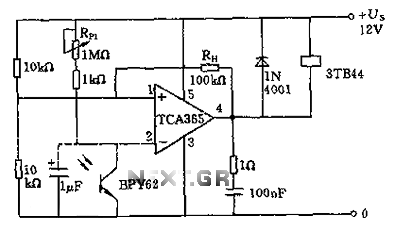
A bridge input circuit utilizing a phototransistor BPY62 and a power operational amplifier is capable of controlling power loads up to 8.5 kW. It features a voltage divider composed of two 10 kΩ resistors, creating a midpoint connection. The...

The core device is a circuit pyroelectric infrared sensor (BH). When it detects infrared radiation from a body, the sensor element responds to changes in temperature. As a thermoelectric element, its self-ferroelectric polarization value changes, causing a discharge of...
This SCADA controller is designed for use with distribution (13.2 kV/4.8 kV) substation transformer breaker positions where an automatic throw-over is present. The RTU voltage is 24V DC. The breaker status and lockout relays operate at 48V DC. The SCADA...
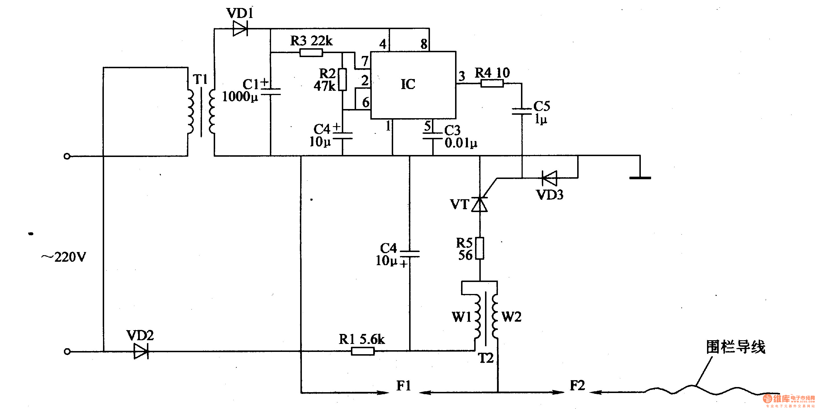
The electric fence control circuit consists of a power supply circuit, a pulse generator, and a high-voltage circuit, as illustrated in Figure 4-27. The power supply circuit includes a power transformer (T1), rectifier diodes (VD1, VD2), filter capacitors (C1,...

The circuit for testing human reaction speed is illustrated in the figure. It includes NAND gates D25 and D26, along with other components that generate a multivibrator output clock pulse with a period of approximately 50 milliseconds. The circuit...
This small circuit is designed to verify the basic functionality of an infrared remote control unit. The circuit utilizes a straightforward approach by connecting a piezo buzzer directly to an IR receiver integrated circuit (IC). This configuration is as...