
Motorcycle anti-thief alarm circuit (8)
The motorcycle anti-theft alarm circuit is designed to provide security for motorcycles by detecting unauthorized movement or tampering. The core component of the system is the anti-theft detection circuit, which utilizes a piezoelectric vibration sensor. This sensor is sensitive to vibrations and can detect when the motorcycle is being moved or tampered with.
When the sensor detects vibrations, it sends a signal to the control circuit, which processes the input and triggers the alarm system. The control circuit is responsible for managing the various functions of the alarm, ensuring that the system responds appropriately to detected threats.
The sound generator produces an audible alarm when activated, alerting the owner and potentially deterring thieves. This component is often designed to create a loud and attention-grabbing sound to maximize its effectiveness. The audio oscillator is responsible for generating the specific sound frequencies used by the sound generator, ensuring that the alarm is both effective and distinctive.
The power amplifier output circuit amplifies the audio signal from the sound generator, ensuring that the alarm can be heard over a significant distance. This amplification is crucial for the alarm's effectiveness, particularly in noisy environments where the alarm needs to be prominent.
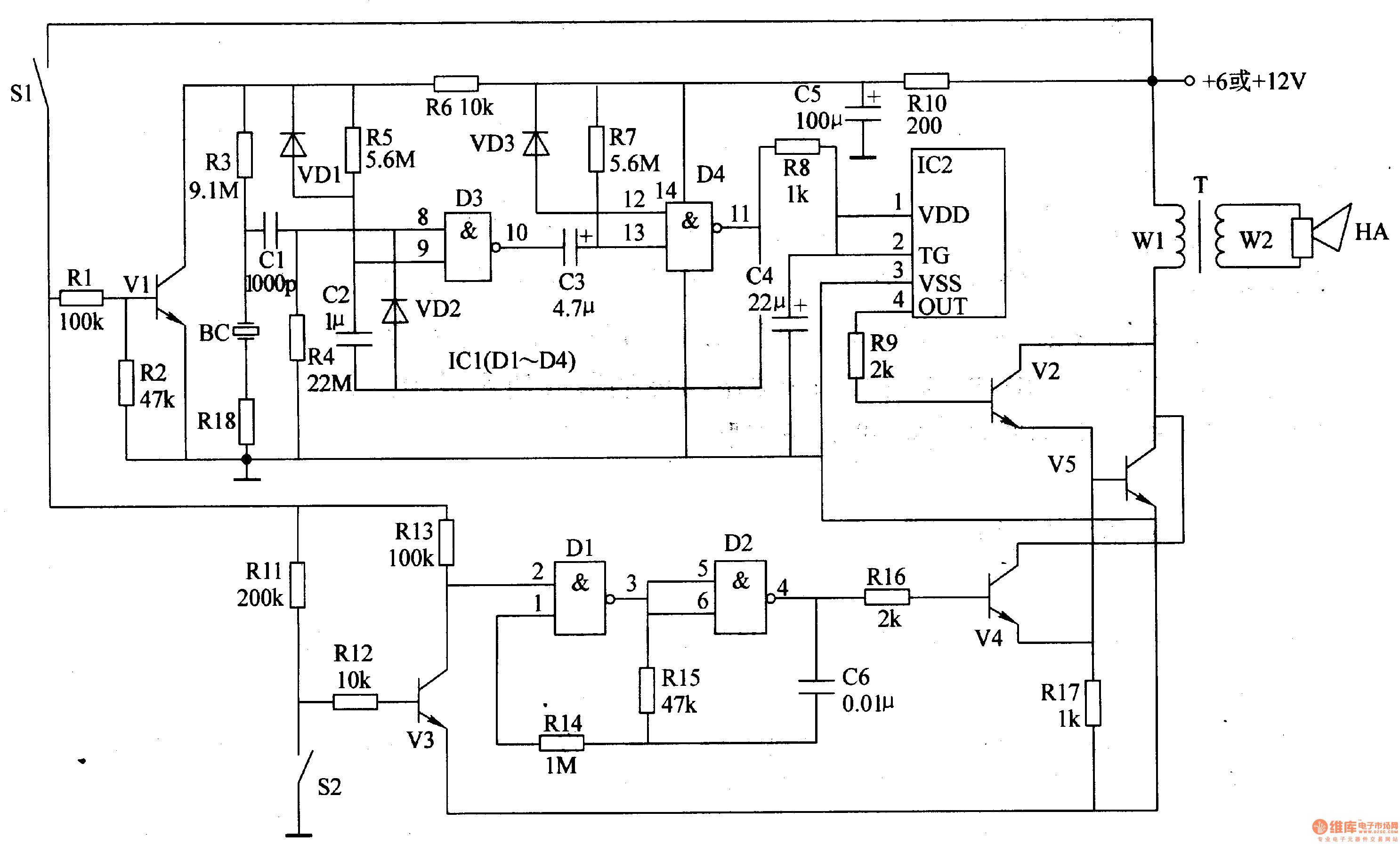
Overall, the motorcycle anti-theft alarm circuit integrates these components into a cohesive system that enhances motorcycle security by providing real-time alerts in the event of unauthorized movement.The principle of the circuit The motorcycle anti-thief alarm circuit is composed of the anti-theft detection circuit, the control circuit, the sound generator, the audio oscillator and the power amplifier output circuit, the circuit is as shown in figure 7-91. The anti-theft detection circuit is composed of the piezoelectric vibration sensor BC, the resist.. 🔗 External reference
Related Circuits
Individuals seeking a distinctive gift for Christmas and New Year may find this project appealing. Certification of this project will undoubtedly create a preference for it. The project in question appears to be a creative endeavor aimed at providing a...
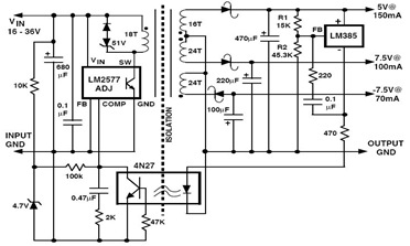
The following figure illustrates an example of a three-output flyback regulator constructed using the LM2577, which features electrical isolation between the input and output voltages. The circuit diagram specifies a voltage of 5V. Electrical isolation between the input and...

The circuit presented is a digital fan regulator that offers five speed levels, similar to conventional fan regulators. This ceiling fan controller utilizes readily available components. An optional 7-segment display with associated circuitry is included to show the selected...
Using high-beam headlights while driving on the highway can significantly enhance visibility; however, they may pose a blinding risk to other drivers. This straightforward circuit can be integrated into the headlight switch to enable automatic switching between high and...
The modular Portable Mixer design featured on these web pages has gained popularity among many amateurs; however, some users have requested a simpler device primarily for mixing mono signals. This design aims to meet those requirements, incorporating three inputs...

Low Ripple Regulated Power Supply Circuit Diagram. This circuit can be employed in applications requiring high current with minimal ripple voltage, such as in high-powered class AB amplifiers where high-quality audio reproduction is essential. The low ripple regulated power...
Warning: include(partials/cookie-banner.php): Failed to open stream: Permission denied in /var/www/html/nextgr/view-circuit.php on line 713
Warning: include(): Failed opening 'partials/cookie-banner.php' for inclusion (include_path='.:/usr/share/php') in /var/www/html/nextgr/view-circuit.php on line 713