
Digital Fan Regulator Circuit PCB
The digital fan regulator circuit effectively manages fan speed through a straightforward user interface and reliable component selection. The use of dual JK flip-flops allows for precise counting and toggling behavior, essential for maintaining the desired speed levels. The NE 555 timer, configured as a monostable multivibrator, ensures that each press of the switch generates a clean pulse, preventing erroneous counts due to switch bounce. The 3-line to 8-line decoder (IC74138) efficiently translates the binary count into control signals for the relays, enabling smooth transitions between speed settings.
The relays, controlled by the transistors, provide isolation between the low-voltage control circuitry and the high-voltage fan circuit, ensuring safety and reliability. The tapped resistor RT is critical for adjusting the fan speed and can be tailored based on the fan's specifications, allowing for a customizable user experience. The integration of a 7-segment display enhances usability by providing real-time feedback on the current speed setting, making it easier for users to select their preferred speed.
Overall, this digital fan regulator circuit exemplifies a practical application of digital electronics in everyday appliances, combining functionality with user-friendly features. The design is scalable and can be modified to accommodate additional features, such as remote control capabilities or integration with smart home systems, further enhancing its versatility and appeal.The circuit presented here is that of a digital fan regulator, variable to provide five speed levels as catered for in ordinary fan regulators. The circuit of ceiling fan controller makes use of easily available components. An optional 7-segment display with its associated electronic circuitry has been provided to display your choice of fan speed.
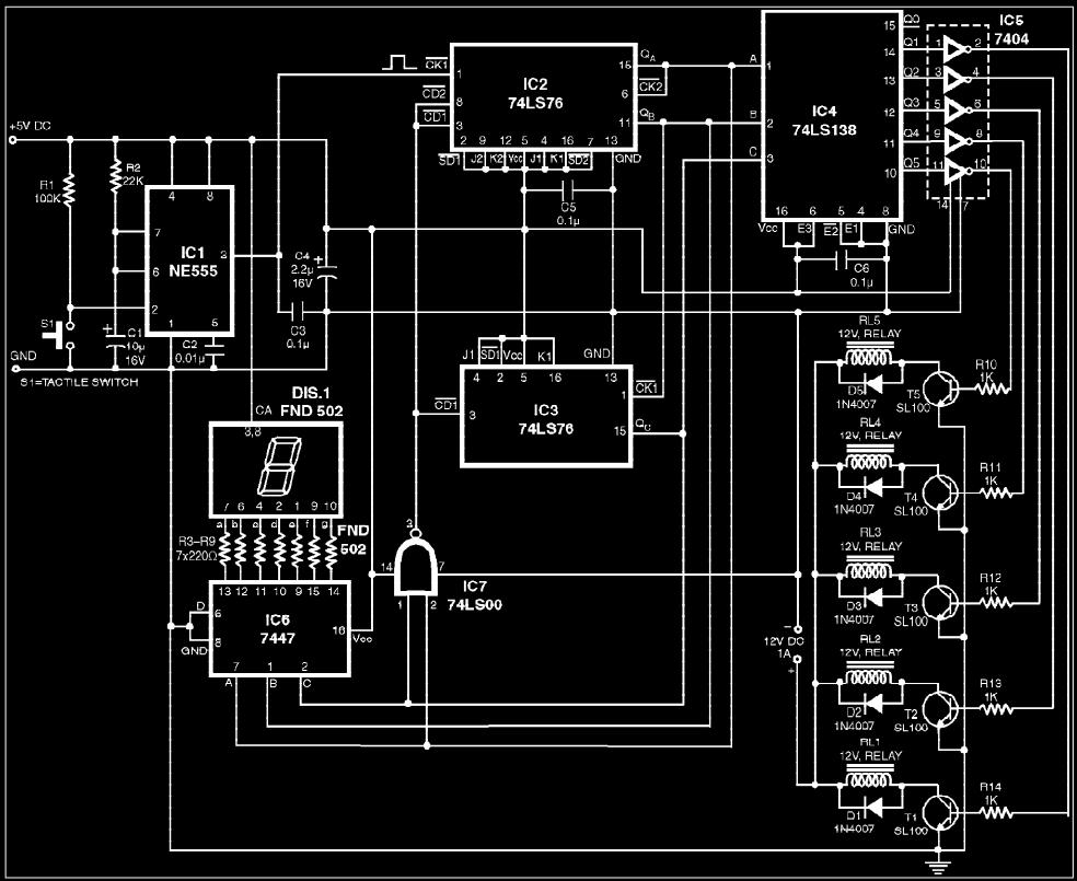
The heart of the circuit is a modulo-6 binary counter, built around IC2 and IC3 (IC 7476) which are dual JK flip-flops. The counter counts up in a straight binary progression from 000 to 101 (i. e. from 0 to 5) upon each successive clock edge and is reset to 000 upon next clock. The count sequence of the counter has been summarized in Table I. Each flip-flop is configured to toggle when the clock goes from high to low. Let us begin with the assumption that the counter reads 000 at power on. The monoshot built around IC1 (NE 555) provides necessary pulses to trigger the counter upon every depression of switch S1.
Upon the arrival of first clock edge, the counter advances to 001. The outputs of the counter go to IC4 (IC 74138), which is a 3-line to 8-line decoder. When IC4 receives the input address 001, its output Q1 goes low, while other outputs Q0 and Q2 through Q7 stay high. The output Q1, after inversion, drives transistor T1, which actuates relay RL1. Now power is delivered to the fan through the N/O contact RL1/1 of relay RL1 and the tapped resistor RT.
For the tapped resistor RT, one can use the resistance found in conventional fan regulators with rotary speed regulation. The outputs of the counter also go to IC6 (IC 7447), a BCD to 7-segment code converter, which, in turn, drives a 7-segment LED display.
When switch S1 is depressed once again, the counter advances to count 010. Now, the output Q2 of IC4 goes low, while Q0, Q1 and Q3 through Q7 go high or remain high. This forces transistor T2 to saturation and actuates relay RL2. The display indicates the counter output in a 7-segment fashion. The counter proceeds through its normal count sequence upon every depression of switch S1 up to the count 101. When switch S1 is depressed once again, normally the counter should read 110. But the two most significant bits of the counter force the output of NAND gate (IC7) to go low to reset the counter to 000.
The counter now begins to count through its normal sequence all over again, upon every key depression. 🔗 External reference
Related Circuits
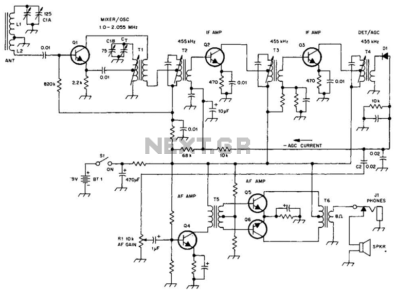
A schematic of a typical transistor AM radio is presented. This circuit utilizes npn transistors. It is a generic circuit; hence, specific values for some components are not provided. This circuit serves as a reference point for experimenters. The schematic...
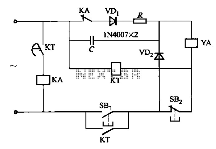
AC solenoid DC circuit operation operates similarly to a DC contactor circuit, but the AC solenoid pull circuit is illustrated in the provided figure. The capacitance C is generally between 1-10 microfarads (µF), with a minimum of 20 microfarads...
The following circuit illustrates an Ultrasonic Sensor Switch circuit diagram. This circuit is based on the 555 Timer IC for the Ultrasonic Transmitter. The Ultrasonic Sensor Switch circuit utilizes a 555 Timer IC configured in astable mode to generate ultrasonic...

This is a white LED lamp that activates when the telephone rings. The cool white light aids in locating the phone in low-light conditions and assists in managing clutter. The circuit for the white LED lamp that illuminates upon a...
The circuit detects a sudden shadow falling on the light-sensor and sounds the bleeper when this happens. The circuit will not respond to gradual changes in brightness to avoid false alarms. The bleeper sounds for only a short time...
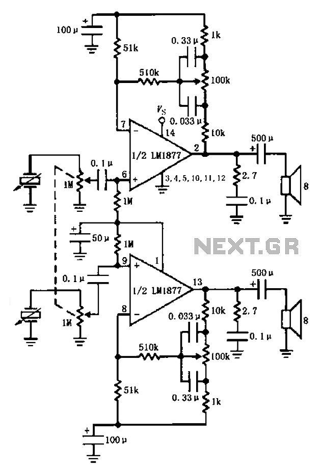
A bass player setup utilizing a stereo control is implemented through an LM1877 amplifier circuit. A cermet stereo microphone pickup is used to capture audio signals from a stereo turntable, with left and right channel outputs. The audio signals...