
motorcycle headlight with single spdt relay
To wire an H4 xenon bulb using a single 30-amp SPDT relay, the following components and connections are required:
1. **Components**:
- H4 60/65-watt xenon bulb
- 30-amp SPDT relay
- 30-amp fuse holder with appropriate fuse
- Wiring (16 AWG or thicker is recommended for high current)
- Connectors and terminals as needed
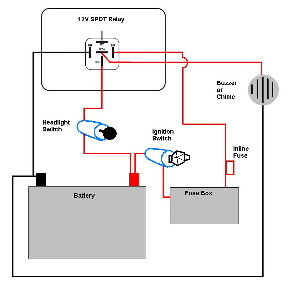
2. **Relay Pin Configuration**:
- Pin 85: Relay coil negative (ground)
- Pin 86: Relay coil positive (trigger)
- Pin 30: Common terminal (input power)
- Pin 87: Normally open (NO) terminal (high beam)
- Pin 87a: Normally closed (NC) terminal (low beam)
3. **Wiring Steps**:
- Connect the battery positive terminal to the fuse holder and then to pin 30 of the relay. Use a fuse rated for 30 amps to protect the circuit.
- Connect pin 87 of the relay to the high beam terminal of the H4 xenon bulb.
- Connect pin 87a of the relay to the low beam terminal of the H4 bulb.
- Connect the ground terminal of the H4 bulb to the negative battery terminal or the bike's chassis.
- Connect pin 85 of the relay to the bike's ground.
- Connect pin 86 to the switch that will control the high/low beam function. This switch can be the original headlight switch of the bike. When the switch is in the high beam position, it will energize the relay and connect the high beam terminal to the power. In the low beam position, the relay will connect to the low beam terminal.
4. **Operation**:
- When the high beam is activated, the relay is energized, connecting power to the high beam terminal of the bulb.
- When the low beam is activated, the relay will switch to the low beam terminal, allowing the bulb to operate at a lower brightness.
A schematic diagram can be created based on these connections, ensuring that all wiring is secure and insulated to prevent shorts. This setup provides a reliable method to upgrade the headlight while managing the increased power requirements of the H4 xenon bulb effectively.A bike with 35 watt HS1 bulb and I want to upgrade brightness of headlight so I decided to put H4 60/65 watt xenon bulb. An expert on this forum suggested me to use relays as the new bulb requires more power. I did some google to understand relays and how to wire new headlight with relays, but the confusion is that the links and videos for relay wiring that I found online was for cars and car has two head lights
so they have used two SPDT(Bosch) relay for that but for my bike I need only one bulb so I guess single 30 AMP SPDT relay would be enough but I am confused what should be the circuit diagram for single SPDT relay to control headlight HI-LO beam. I know instead of making setup from scratch by myself many of you would suggest me to go for Eastern Beaver H4 kit but the problem is that I am in India and I dont have any paypal account to pay for kit and even not sure whether this kit would be economical for me or not thats why I decided to make this setup by myself.
I have 30amp SPDT relay, 30amp fuse holder and H4 xenon bulb and I need help of the experts on this forum to please guide me on how wire new headlight. A simple circuit diagram would be enough like this one at earlycuda. org: 🔗 External reference
Related Circuits
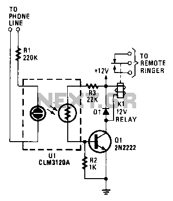
When the phone rings, the ring signal from the telephone company activates a neon lamp within a CLM3120 optocoupler. This activation results in a decrease in the resistance of the CdS cell output of the device, which in turn...
This component is equivalent to a single-pole electromechanical latching relay with an electrically isolated solenoid. Once activated, the circuit remains in a conductive state even if the line voltage is interrupted for extended periods. A positive reset action necessitates...
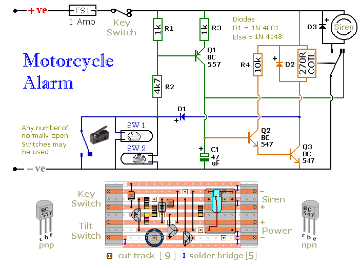
Any number of normally open switches may be used. Fit the mercury switches so that they close when the steering is moved or when the bike is lifted off its side-stand or pushed forward off its centre-stand. Use micro-switches...
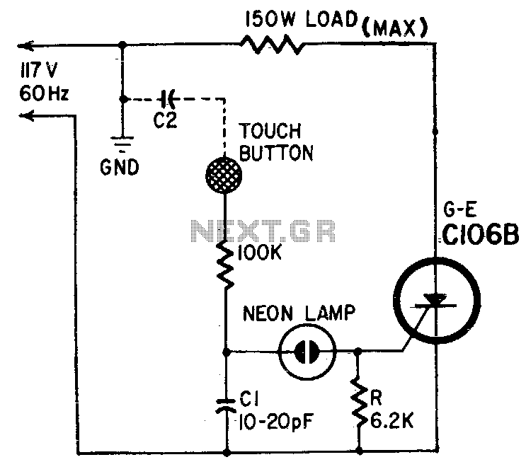
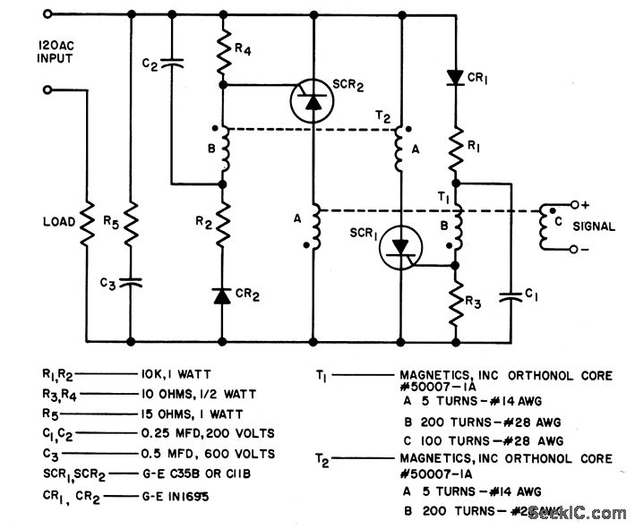
Capacitor Cl and body capacitance (C2) of the operator form a voltage divider from the hot side of the AC line to ground. The voltage across Cl is determined by the ratio of Cl to C2. A higher voltage...
A bandpass filter allows a specific range of frequencies to pass while rejecting frequencies that fall outside the upper and lower limits of the passband. The frequencies that are permitted to pass are referred to as the passband, which...
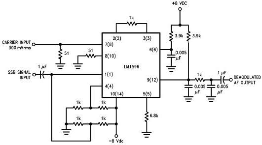
A simple single sideband (SSB) suppressed carrier demodulator circuit can be constructed using the LM1596 balanced modulator-demodulator integrated circuit (IC). The carrier signal should be applied to the carrier input port at an optimal level of 300 mVrms to...
Warning: include(partials/cookie-banner.php): Failed to open stream: Permission denied in /var/www/html/nextgr/view-circuit.php on line 713
Warning: include(): Failed opening 'partials/cookie-banner.php' for inclusion (include_path='.:/usr/share/php') in /var/www/html/nextgr/view-circuit.php on line 713